Nintendo DS Lite Black Screen

After my Nintendo DS Lite fell from a meter, it ceased to show anything on the screen(s) as I tried turning it on. A quick search on the internet didn’t quite reveal a goto solution.

Problem symptoms:

  • Upper and lower screen remains black
  • Charging seems to work
  • Green power LED lights up as the handheld is turned on
  • There is a short faint pop audible from the speakers as if the audio amplifier circuitry is operational. This same pop is also audible on functioning units.

Proposed solutions from the internet:

  • Check the fuses

This is a simple one. The board has 2 or 3 fuses which can be beeped with a multimeter. Mine were all fine.

  • Check the displays

Due to the fall something could have happened to the display or cable of the top screen. Finding out if this was the problem would require me to dismantle the unit quite a lot and find replacement displays. Too much of a hassle.

  • Check/replace the battery.

It still has the original battery and is many many years old. Last time before it broke I remember it to run out of juice fast. I bought a replacement battery from China. The unit still didn’t turn on. (but at least I’d have a replacement if I’d ever manage to fix it)

  • Put a piece of cardboard under the DS cartridge socket.

Due to the fall some solder joints might have cracked which the pressure of the cardboard was supposed to fix. Sounded like an unreliable joke but tried it anyway. No result.

  • My solution: Replace the wifi module.

This one seemed far fetched. Apparently the wifi module can break at a fall? I looked Aliexpress and found them dirt cheap so I ordered 2 right away. I replaced the one in my DS and it just turned on again. Who would’ve known.

Trust GXT 28 Trigger Repair

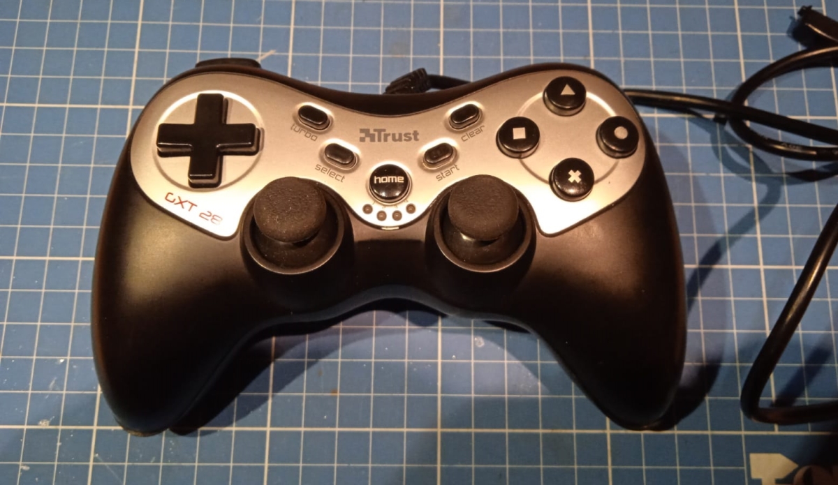
Found this USB game controller at the thriftstore with some fun functions like actual analog feeling triggers and built in TURBO mode. When plugging it in and going to any keypad tester website, I stumbled upon a problem: The right trigger was not responsive (https://gamepadtest.com/):

I reckoned something was wrong with a solder pad or even worse, mechanical issues with the physical button. So let’s screw it open and see!

There are 6 screws to deal with, of which one hidden under the sticker.

Disgusting! Anyway, not a lot of stuff to see here without screwing it open even further. As I am not interested in a full teardown and just fixing the trigger, this is as far as we’ll go.

They were quite ambitious with this one in design, yet didn’t fully take advantage of its potential. For example, where the USB cable comes in is a footprint laid out for a USB input so you could use any external USB cable with it. This controller has a fixed cable.

Another interesting thing is how to the left and right are big pads laid out, possibly to connect 2 DC rumble motors to. Even in the plastic enclosure in the lower left and right of the picture, is visible how there are compartments which would fit these motors.

With two red arrows I indicated problematic spots. To the right a ground pad that shorts towards the CS or chip select pin of this controller. I rather have this CS pin being taken care of by design than an actual short by solder mistake. I will remove this short and assume it will not break anything.

The second and more important arrow points towards the wires that lead from the controller PCB to the right shoulder and trigger button PCB. Let’s zoom in!

We are greeted with a wire that is floating in the breeze, no wonder it doesn’t work! To make sure this cheapo flatcable won’t ruin my day in the future, I decided to replace the whole thing with a fresh flatcable.

The cable didn’t like to get soldered and got its insulation a bit molten at the controller PCB side, but electrically it is all fine… I promise!

A quick view of the other side of the pad. Pretty basic setup. Two carbon pads that get shorted when pressing a button by a rubber dome switch which I removed.

Job’s done!

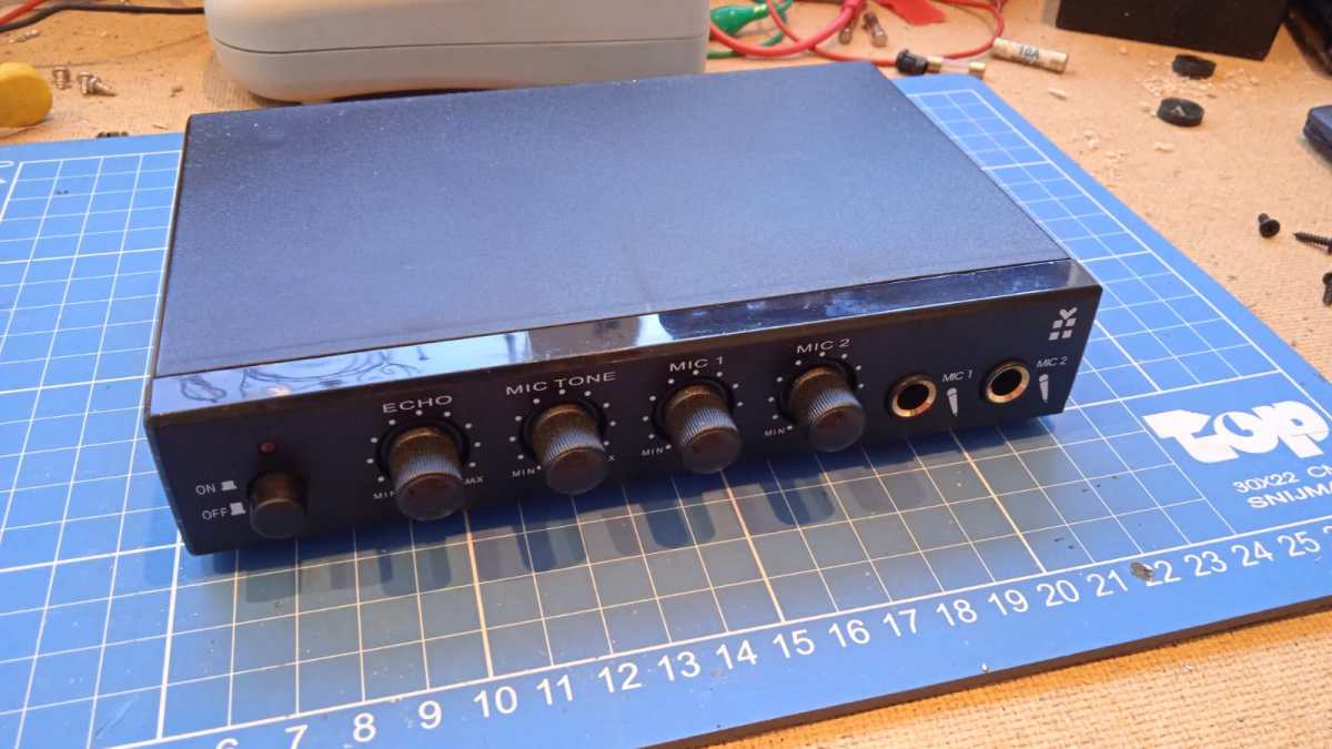
DP Specials Karaoke Set Module

Dutch thriftstores have these now and then for nearly no money because they lack the microphones, power supply etc. etc. but they house one very particular part which I’m interested in.

But what is it? Just a main module for basic karaoke parties. Plug in 2 microphones, set the tone (variable low pass filter) and individual mic volume. And as a bonus you can add in an echo/delay at a fixed delay time and feedback level. The module is meant to sit between a game console or DVD player (just anything that can play shitty karaoke songs) and then have its audio fed to a tv or whatever as it also has a video in pass-through.

Teardown

Removing the top (by removing 4 philips head screws from the bottom) reveals all the through-hole parts including a particular DIP IC. This is a CD2399GP which is similar to a PT2399 but from another manufacturer. As all the PT2399s I bought from China gave me various issues, desoldering these becomes very worthwhile.

Note how there has been a patch at D1 in the top right corner. Has someone been in here before or did someone had to make sure it passed quality control?

Not a lot else to see here, some filtering caps and the pots. More interesting is the little cutout in the PCB and the shape of what might’ve been a battery holder in the bottom of the module. These enclosures are probably used for many different devices.

On the bottom a lot of SMD of which mostly opamps do the necessary audio trickery. Really not anything worthy to look into further.

The backside reveals how the audio and video pass-through works. Unit runs on 9V center positive adapters. This might raise questions as to why there is a 78L09 on board.

AudioSonic CL-249 Alarm Clock Radio

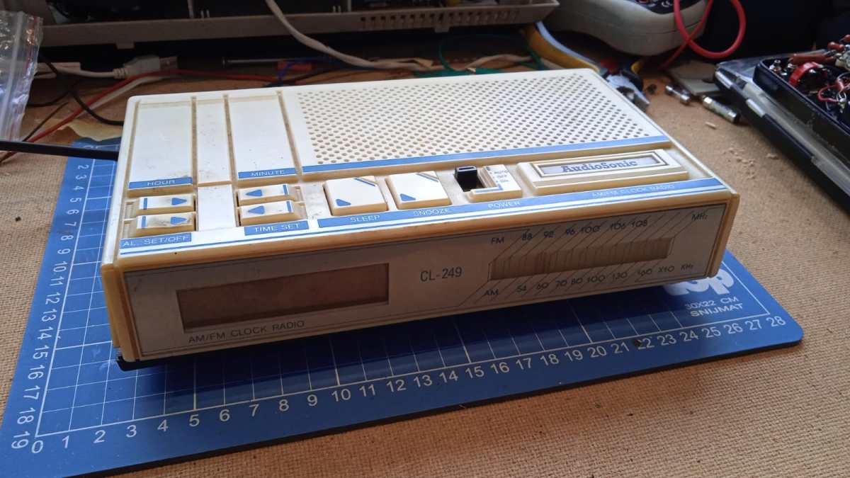
I’ve seen this piece of crap lying around at the thriftstore for months. Even the employees started to notice it and decided to slap a sticker on it: 50 eurocents. Well, yellowed buddy, you can come with me.

I could not really find any information about this particular alarm clock radio, and I even feel like I am the first on the internet to give any form of unneeded attention to it. Judging from the design, the ICs I bet it is late 80s, early 90s.

Upon plugging it in the whole darn thing didn’t turn on or respond to any button or switch configurations, I would find out later why this is so…

Features

I’m not even going to go in depth on this one. It’s a simple alarm clock radio with all the functionality you would expect from one. Leave a comment if you need details.

Teardown

Opening up is a piece of cake, four or so philips screws and we’re in.

Screwed open

All the interesting stuff in the upper part and the speaker and button interface PCB on the lower part. Tranformer is center tapped with about 9.5V per tap. Lets zoom in further.

Knob PCB

As visible, a simple rubber dome interface of which the former didn’t survive long. Dried out and broken off. Junk.

The main chip

Pretty much all functionality is put into an LM8560 from some funky company. This chip is well documented and is for some still a hobbyist favourite. The display is an LED 7 segment variety.

Absolutely terrific decades old manual children labour.

Amplifier chip and some RF tuning circuitry

The amplifier chip is a KA2201. Pretty much comparable to an LM386: low voltage, low power mono amplifier in DIP8. Also visible some coils, transistors and passives of the RF tuning circuitry. This thing does both FM and AM.

Germanium diodes!

It even has 2 germanium diodes! I can now sell it for a big profit to some guitar pedal enthusiasts.

Backside

Not much to see on the backside. The tuning mechanism and the marking NL-329 AM/F. There is also a marking of some company with “KF” as logo.

Repair

As previously mentioned, the thing doesn’t start up when plugged into mains and the 9v backup battery leads were cut off for some reason. I incidentally found out it actually does turn on when holding the mains cable at a certain angle. I almost feel bad for resurrecting it.

Horay, it is alive

The radio and audio portion of the device works fine. The alarm clock portion however does not as the button pads on the PCB barely react to any for of manual shorting. I’m not motivated enough to debug and repair this.

Xbox 360 Wired Controller Repair

Found me a good deal on a wired 360 controller at the thriftstore. Sadly I found out the darn cable was cut! This often means one of two thing: someone tried to make it wireless and got disappointed or a hobbyist found a catastrophic problem with it and cut it to make sure no one would ever plug it in. “Well!” I yelled, “I am not afraid!”. So here is the journey of fixing this beauty of a controller.

Front view before the operation

As you can see, the poor controller is circumcised. Also as per usual these things are greasy and gunky and disgusting. The X button keep sticking because of all the gunk in its shaft. Have to clean it up later.

Backview with screwholes

Taking it apart is a piece of xbox cake. 6 philips screws around the perimeter and a sneaky one behind a barcode sticker.

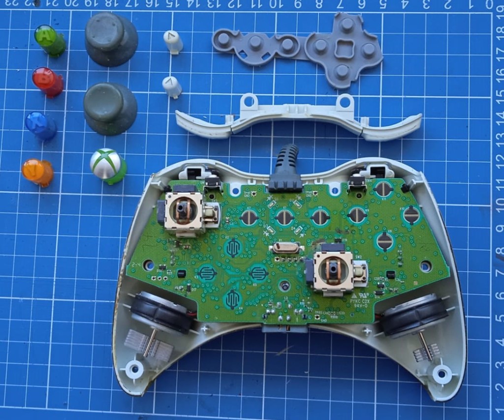
PCB front view

A thing of beauty. Don’t mind the hand gunk on those ridges of the shell from the previous owner. Anyway… In the lower left and right we got our vibration motors. No clue why they’re asymmetrical in size but they probably had their reasons to do this. Maybe one is for gentle vibrations and the other for heavy?

In the upper left and right to the center we got the analog thumbstick mechanisms. It’s a charming design that uses two potentiometers (those gray boxes on the top and left of them) to translate the position of the thumbstick to a X and Y coordinate for the game engines to interpret. These potentiometers are also cause #1 of stick drift. Check my video on it to learn more. To the right are simple tactile switches that are engaged when pressing on the thumbsticks.

PCB back view

So as it’s a basic USB gamepad we luckily don’t have to deal with things too exciting. From left to right, ground (black), data – (green), data + (white) and VUSB (red). My plan is to get rid of this header for the time being and solder in a new cable straight to the solder pins.

My first concern was strain relief. I don’t want to jank the cable and have 4 vias on a cable in my hands. So I had to find out if the strain relief thingy from the old cable assembly could be harvested and fitted on my new USB cable.

Strain relief

I tried tugging the cable out of it and that worked, but as you can see in that hole theres still a tube that makes it way too narrow to fit a new cable in. My plan was to drill it out.

Drilling the strain relief

To my surprise the inside tubing went out without any struggle at all. A great succes! The new cable went in too without any problems (or lube!)

New cable installation

Yeah yeah! It’s not my best work. I had to make sure the shielding was connected to the ground wire but it all fits now. Also added a bit of chinese shrink tubing (which does not shrink even in the fires of hell) to add some isolation to the board.

Connected to a desktop

And we got connection!

Cleaning the buttons and shells

Clean the controller from all the gunk before reassembling it with warm water, mild detergent and the toothbrush of someone you hate.

After the operation

And we got a new clean gamepad to play with!

Imatronic SX3000 Slide Dissolve Unit

Saw this unit lying around at a thriftstore (€5) thinking it had something to do with audio because it had tape written all over it. Then I googled and found something about the Hammond XC3000? Like is it some sort of rotary speaker controller? I got excited and bought it right away to find out later it’s nothing but a so called slide dissolver.

I think the big idea is that back in the day where slide projectors were still a thing, you’d set up 2 of them and used a slide dissolver to switch between the two and make some sort of interesting audiovisual spectacle.

I don’t own any slide projectors and audio intrigues me more than video, so I might reuse the fader controller as some sort of synthesizer ribbon controller.

Anyway, I opened the thing up. It was full of CMOS logic ICs so that was a nice sight. Less nice were the amount of repairs that were done to it. I guess it wasn’t very reliable but important enough for the previous owners to replace chips capacitors and resistors all over the board. Anyway here some shots:

Excuse me for the mess. So we have a hand control input for the fader controller on top there, and a tape input I assume for… audio? The rest of the LEDs and buttons are a mystery to me. The device also uses 50 shades of DIN connectors so there’s no DC input or other simple way to turn it on.

Opening up the fader controller, we see a slide potentiometer with two end switches. I assume they allow you to go to the next slide. There’s also this blue non latching switch labeled “FLASH”. Not a single clue what that’s supposed to do but induce seizures on those watching the show.

Look at that! Quite beautiful if you ask me. Nowadays we’d use a single microcontroller to handle all of this, but back then? Digitial CMOS everywhere.

As I have no clue how this device works, can’t find any schematics or am bored enough to trace the whole machine, I’ll just leave you with a load of closeups of the board!

Sanyo M-787AZ Cassette Recorder

More thrifting. Probably early 70s. Has a battery, DC and AC input which is nice to have. Big volume knob and various interfaces for headphones, microphones and radio.

Front view
Interface of connectors and volume
Backside
View when removing the back lid
I had to desolder or snip some wires to get the board out but I didn’t want to get that far, so this is the best I could do.
PCB sideview
Two transistors in a custom heatsink bolted onto the side
2SB22 SANYO transistor

Standard SR-T115 Cassette Recorder

Another cheap thriftstore find. This 1968 cassette recorder comes with a (electret) microphone and runs on 6VDC. it also has an output for “external “SR” radio”. Whatever that may be.

It works well under low volume but at higher volume it starts squealing and with a bit of artistical input you can make it sound like a formula 1 car.

If anyone has more information or is familiar with this problem and knows a cure, don’t hesitate to leave a comment or contact me!

Front view
In- and outputs
Backside with battery compartment
View when removing the back lid
Close up of the PCB

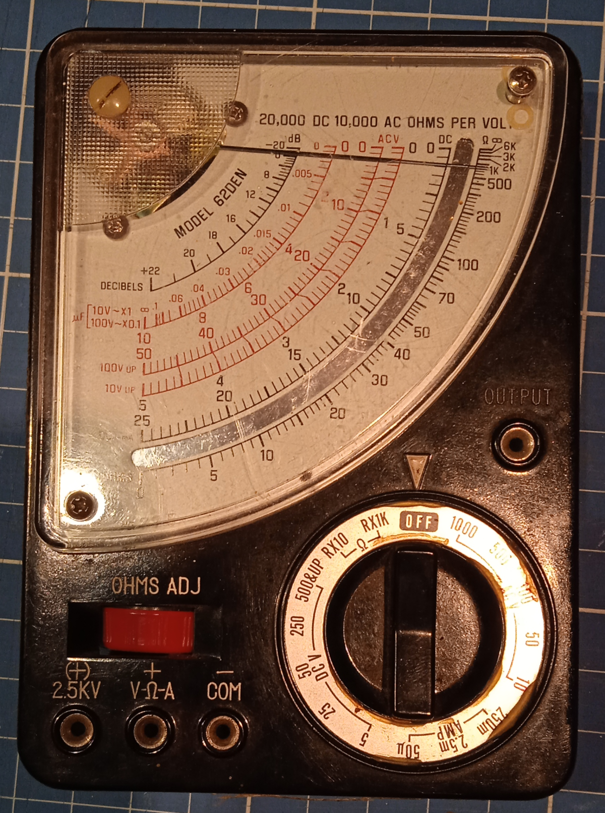
Vielfachmessgerät No. 62DEN Analog Multimeter

A dumpsterdive from a while back of a heavily beaten vintage multimeter. The enclosure is broken but the electronics still look fine. I can’t get the analog panelmeter to nul to 0 tho with the adjustment on the front of the meter. Maybe there are tricks to get that working and have nice new meter!

There isn’t much known about this device but this listing I found on the Radiomuseum website. So In short, 60s german analog multimeter by Ultron-Elektronik GmbH.

Front view
Open back
Germanium zoom (and two back to back black white drops, whatever those may be)

Unknown Dutch 70s Bench PSU

Found this lab bench power supply at work which had a loose current limit pot. So I decided to open it up with the intention to fix this loose pot. But while doing this I might as well document what I could find in there!

Specification

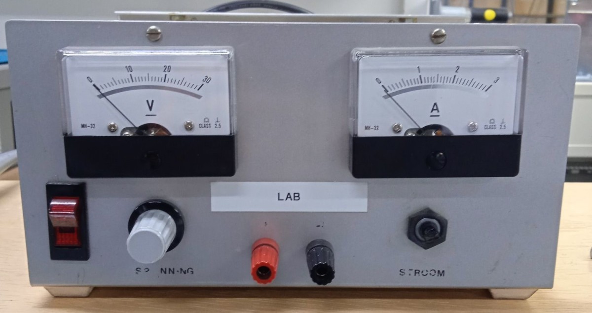
Seems like the PSU is dutch judging by the labels on the front. “Spanning” meaning voltage and “stroom” being current. This also tells us that this is a 30V 3A lab power supply. If anyone knows more about brand, type and year, please contact me 🙂

The outside

Front of the PSU

Two analog panel meters to show voltage and current. I nice chunky power switch with integrated pilot light. Two knobs to set the desired voltage and current limit. And the voltage gets presented at the two banana plug posts that are also screwable to attach wires.

As visible, the knob on the current control pot is removed. I did this so I could reach the nut that makes sure the pot is tight against the chassis and won’t move when the knob is turned or reaches its limits. This nut was loose which led to the knob shifting and rotating around while being operated.

The insides

Top view PSU

In fact not much going on. The panel meters, banana posts and power switch at the top all with nice beefy wires.

Also a nice big transformer with what seems 2 secondary outputs which possibly gets put in series to get a rectified voltage of 33.6V, great for the linear regulators to get the 30v out of.

At the back of the power supply is a connection to mains, a fuse on the primary side and a power transistor (TO-3) which gets mounted on a nice big heatsink out of frame.

Of course the star of the show is the single sided regulator PCB!

Close up of regulator board

There is a big chonky 4700µF smoothing capacitor and a full bridge rectifier in a quite unusual visual arrangement. Probably better for airflow like this.

heatsank socketed DIP IC

I didn’t take the time to remove the heatsink from that DIP IC but it’s most definitely some kind of linear voltage regulator but can also be an opamp. Let’s just admire the view of a heatsank DIP that’s also put on a socket!

One of the transistors, a BD140 accompanying the TO-3 on the back. I’m not sure what TO-3 that is, could be a chonky pass transistor or even a TO-3 LM317.

I will take more pictures and fetch more details whenever I get the chance. If anyone knows more about this PSU, please let me know 🙂

Update!

Here is another batch of pictures, enjoy!

View of the shunt resistor, 0.22 ohms
470 and 10k linear pots
LM723, up to 40V input, 2 to 37v output linear regulator in DIP (was hidden under the heatsink)
External pass transistor, a good ol’ 2N3055 for the needed oomph