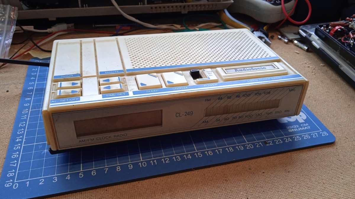
I’ve seen this piece of crap lying around at the thriftstore for months. Even the employees started to notice it and decided to slap a sticker on it: 50 eurocents. Well, yellowed buddy, you can come with me.
I could not really find any information about this particular alarm clock radio, and I even feel like I am the first on the internet to give any form of unneeded attention to it. Judging from the design, the ICs I bet it is late 80s, early 90s.
Upon plugging it in the whole darn thing didn’t turn on or respond to any button or switch configurations, I would find out later why this is so…
Features
I’m not even going to go in depth on this one. It’s a simple alarm clock radio with all the functionality you would expect from one. Leave a comment if you need details.
Teardown
Opening up is a piece of cake, four or so philips screws and we’re in.
Screwed open
All the interesting stuff in the upper part and the speaker and button interface PCB on the lower part. Tranformer is center tapped with about 9.5V per tap. Lets zoom in further.
Knob PCB
As visible, a simple rubber dome interface of which the former didn’t survive long. Dried out and broken off. Junk.
The main chip
Pretty much all functionality is put into an LM8560 from some funky company. This chip is well documented and is for some still a hobbyist favourite. The display is an LED 7 segment variety.
Absolutely terrific decades old manual children labour.
Amplifier chip and some RF tuning circuitry
The amplifier chip is a KA2201. Pretty much comparable to an LM386: low voltage, low power mono amplifier in DIP8. Also visible some coils, transistors and passives of the RF tuning circuitry. This thing does both FM and AM.
Germanium diodes!
It even has 2 germanium diodes! I can now sell it for a big profit to some guitar pedal enthusiasts.
Backside
Not much to see on the backside. The tuning mechanism and the marking NL-329 AM/F. There is also a marking of some company with “KF” as logo.
Repair
As previously mentioned, the thing doesn’t start up when plugged into mains and the 9v backup battery leads were cut off for some reason. I incidentally found out it actually does turn on when holding the mains cable at a certain angle. I almost feel bad for resurrecting it.
Horay, it is alive
The radio and audio portion of the device works fine. The alarm clock portion however does not as the button pads on the PCB barely react to any for of manual shorting. I’m not motivated enough to debug and repair this.
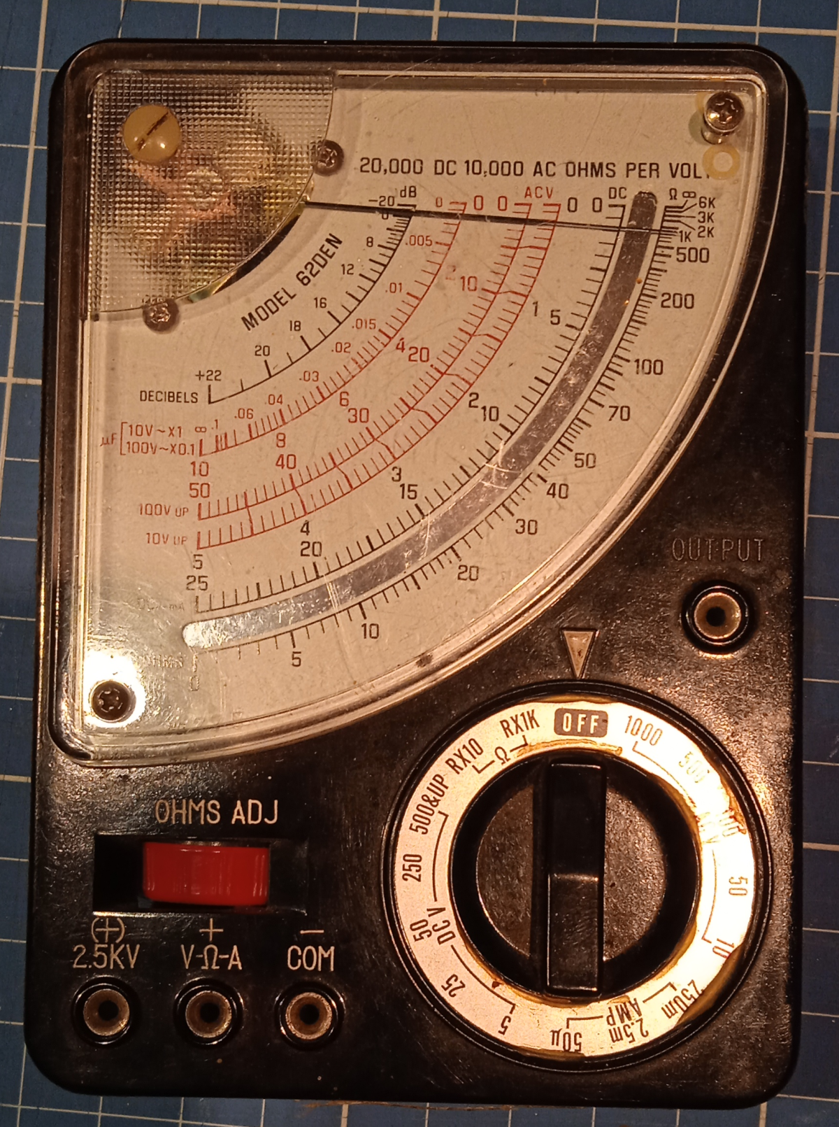
A dumpsterdive from a while back of a heavily beaten vintage multimeter. The enclosure is broken but the electronics still look fine. I can’t get the analog panelmeter to nul to 0 tho with the adjustment on the front of the meter. Maybe there are tricks to get that working and have nice new meter!
When you get into vintage effect pedals etc. you might get to know the amazing germanium diode. These diodes are truly worse in every way compared to silicon diodes, and thus aren’t being produced anymore. This makes them a treasure for those who are chasing the vintage tone. Luckily here and there germanium diode surplusses are still being sold with nice profit margins.
But what is so special about germanium? Well, people claim that they clip “softer” than silicon diodes. This makes your tone sound “smoother” and whatever. In my post about testing diodes it is clear that the knee (slope) of germanium diodes is indeed smoother than those of silicon diodes so that’s one way to prove that it has “some” impact on your tone. But can’t we emulate this soft knee in some way?
The blogpost also showed how you can simply put diodes in series to double the forward voltage, but also make the knee softer. Putting 4 or more silicons in series gets you close to the softness of a germanium, but with a forward voltage of 2.8V.
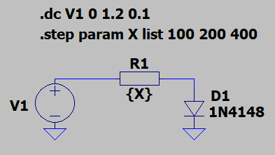
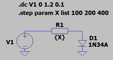
So let’s first put it to the test in LTSPICE. I take a simple voltage source and put a resistor in series with a diode to ground.
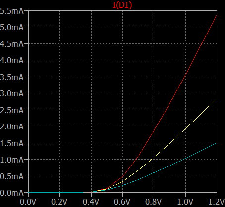
The resistor will be stepped through with 100, 200 and 400 ohms in one plot. The DC sweep is set from 0V to 1.2V with 100mV increments.
In the above plot the VI curve of the 1N4148 silicon diode is visible. The steepness of the curve and thus the knee gets softer with more resistance. A good sign! Now let’s check for a germanium 1N34 diode:
The setup is exactly the same as used for the silicon 1N4148 diode.
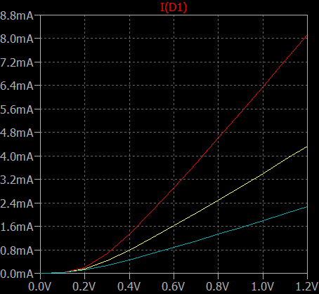
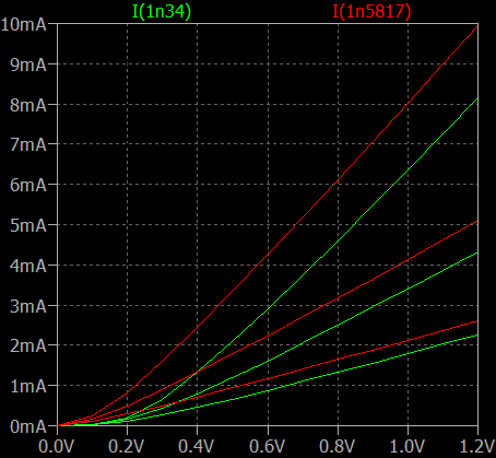
As you can see the forward voltage is way lower but also the steepness of the curves can be altered by changing the series resistance. Now it’s interesting to make a comparison to the two by plotting them both:
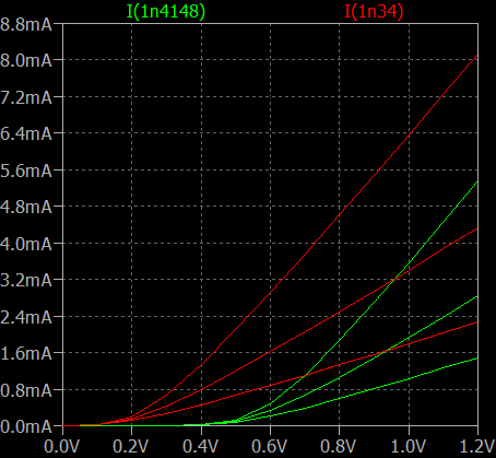
Alright, looks promising. Curves are pretty much the same, the forward voltage is different tho… This can be easily fixed by changing the general purpose silicon 1N4148 diode into a schottky diode. In this case a much used schottky diode is the 1N5817. Let’s plot it against the germanium 1N34:
Holy moly! That’s a beautful sight ain’t it? Almost seems like the 1N5817 with series resistance is a better diode for your tone than a germanium!
Well, alright… a basic LTSPICE simulation might not say everything. Let’s move things to the real world!
Breadboard prototype
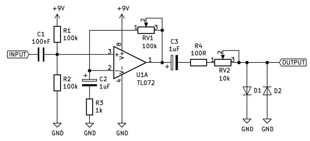
To test this theory in real life I took a simplified and adapted version of the Distortion+ schematic which is nothing more than a non inverting opamp amplifier with some DC biasing for audio signals:
At the input is a sinusoidal signal of 200mVpp @ 1kHz. The scope is probing at the output, to see the waveform across the clipping diodes. The gain is set so the waveform gets moderately clipped.
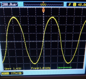
In measurement #1 RV2 is removed and D1 and D2 are replaced with AA119 germanium diodes. The waveform across the diodes at the output will be the reference for measurement #2, where I will try to finetune RV2 in combination with 1N5817 schottky diodes, to get a similar waveform. The waveform across the germaniums with 100 ohms series resistance is as follows:
It’s visible how theres somewhat distortion going on and thus the waveform is nicely clipped.
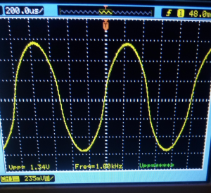
Now I reintroduce the potentiometer VR 2and replace the germaniums with 1N5817 schottky diodes. I will try my best to trim VR2 so it looks like the germanium waveform:
Blimey! The similarities are shocking. Is it this easy to get a cheapo germanium? As far as I can tell yes, the prove is in the pictures. In this case there was a total series resistance of abou 170 ohms with the schottky diode, so not a lot is needed to get the desired effect.
Conclusion?
Ofcourse to really determine if these waveforms are similar, they have to be processed with some kind of spectrum analyzer and check each and every harmonic. But as I don’t have the gear for that I quietly assume that you can easily donate your germanium diodes to the nearest museum or you know, resell them with an even bigger profit margin to some audiophool who’s so obsessed by the germanium placebo that they’re willing to pay a good price.
Me and Dylan and David from the DIY guitar pedal/effects community decided to see for ourselves what the fuzz is about regarding diodes and their “softness”. Why do people like germaniums over silicons? What is the effect of multiple diodes in series? How exactly does the PN junction of a MOSFET look like? All these questions and more will be answered.
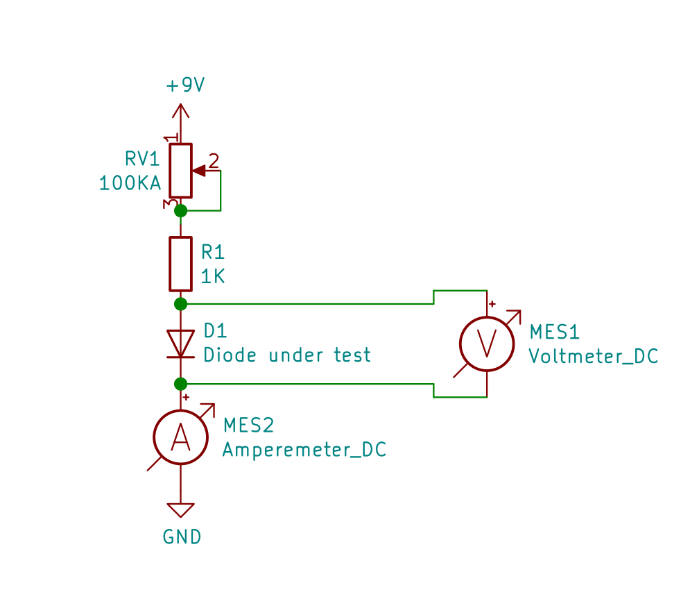
Test setup
Test setup
Tools and equipment:
– Two multimeters (Voltage and current (mA))
– Stopper resistor (100 – 1k)
– Variable resistor (100k)
– PSU (9V battery or lab PSU 0-20V (RECOMMENDED))
– Breadboard + jumperwires and crocodile clips (RECOMMENDED)
By varying the power supply or RV1 it is possible to alter the current through the DUT (Diode Under Test). We measured and noted the voltage across the diode at 4 points: 0.1mA, 1mA, 5mA & 10mA.
For more precision measure 3 or more of the same diode type and average the results.
Overview
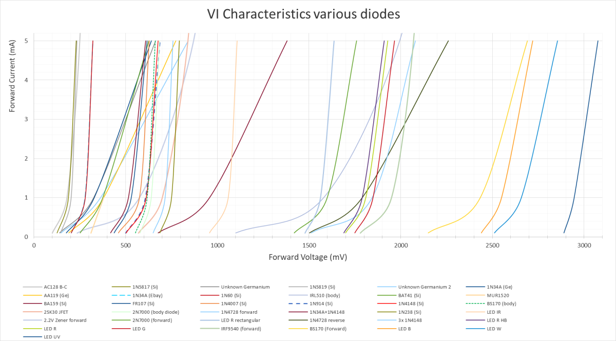
In the following image are all diodes visible we have tested. These are various general purpose silicon, germanium, zener and other semiconductors (Click for bigger image!).
VI characteristics of various PN junctions in semiconductors
In the remainder of this post the curves will be grouped and interesting relations will be further elaborated.
(Fake) Germaniums and Schottkys
We know that germanium and schottky diodes are characterized by having a very low Vf of around 100-200mV. What makes germaniums so much more interesting than silicons is that they are very soft at clipping which to some guitarists create audible differences to their tone. This is visible in the graph by the steepness of the curves.
VI characteristics of Germaniums and schottkys
If you are not sure if your diode is really a germanium or just a schottky, you can do the test as described above and find out! This way we found out some unmarked diodes (Ge 1 through 4) were germaniums and more importantly, 1N34A diodes advertised on Ebay as “germanium” were just 1N60 schottkys with their markings rubbed off! This is why you cannot judge a germanium on just their Vf!
Another interesting relation is how a BAT41 silicon schottky diodes has similar steepness as germanium diodes and could be used as germanium replacement.
When combining diodes you can get some very interesting results. Two 1N34A germaniums in series result double the Vf but also less steepness which results in the equivalent diode being even softer. If you want best of both worlds (High Vf thus high output signal and softness) you can put a silicon in series with a germanium.
Silicon
This very happy and colorful graph shows all the silicon diodes we measured.
VI characteristics of various silicon diodes
Note how silicons have a rather steep curve and the schottky diodes (1N5817, 1N5819, 1N60 & BAT41) have a very low forward voltage. The BAT41 once again shows that it might as well be regarded as a germanium diode with its softness. I’d also like to take a moment to note that 1N4148 silicon diodes are the same as 1N914 silicon diodes.
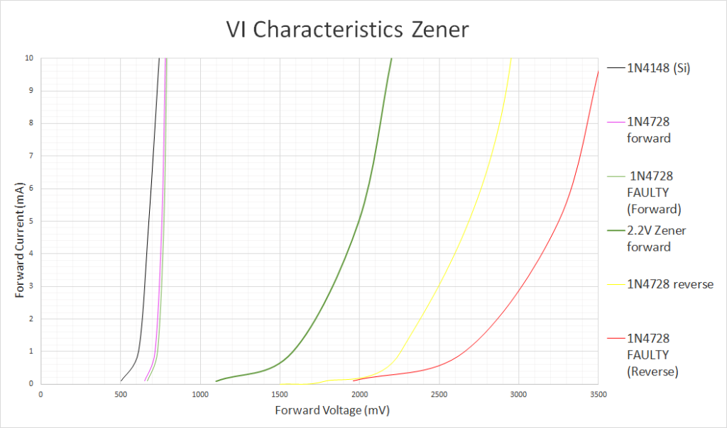
Zener
Zener diodes can be used in two ways: reverse and forward bias. The forward bias will result in a regular forward voltage of a silicon diode but the reverse bias will result in a curve that slowly reaches the zener voltage. The higher the rated zener voltage, the less current is needed to reach it.
VI characteristic Zener diodes
In the above graph a regular 1N4148 silicon diode is used as reference. It is visible that zener diodes in reverse bias are rather softish but we also needed quite a lot of current before they eventually reached their zener voltage (outside the graph). There are two types of 1N4728 tested. These are 3.3V zener diodes (at 70mA…) of which one legit kind eventually reached 3.3V but the faulty chinese ones reached 4.3V at 100mA! This way I found out that I bought faulty zeners a few years back!
Note that one zener diode can theorethically be used to clip both sides of the waveform, one at the forward bias voltage and one at the reverse bias voltage (zener voltage).
Light Emitting Diodes (LEDs)
Also LEDs are beloved in the guitar pedal community as they allow plenty of headroom and clip hard. Sometimes they even light up when theyre being drive hard enough!
VI characteristics various LEDs
Because the color of an LED is controlled by the band gap of the PN junction, it’s logical that the forward voltage is analoguous to the spectrum of the visible light. Funfact: there is a good chance all diodes are LEDs, many just dont emit photons with a wavelength we can see!
Using LEDs as clippers is really a matter of taste and how much output volume/headroom you want.
MOSFET and JFET
Some pedalbuilders thought it was an interesting idea to use PN junctions inside of FETs as clippers. This is because they tend to be a little softer than a regular silicon diode.
VI characteristics variouts FETS
When using the body diode of the FETs it is visible that they pretty much behave like a regular silicon diode like the 1N4148. Using the forward biased PN junction of these FETs result in less steep curves. Use the 1N34A germanium diode and 1N4148 silicon diode as reference for the FET curves.
Let’s put them in series!
As already briefly discussed at the germanium diodes, it is a common practice to put multiple diodes in series to alter the forward voltage and softness of the equivalent diode.
VI characteristics series diodes
Using the 1N34A (Ge) and 1N4148 (Si) as referencee it is visible what the effect is of putting diodes in series. Ofcourse many more combinations are possible: Zeners with germanium, LEDs with schottkys, Silicons with FETs but we just took a few to prove the point of putting diodes in series.
Putting germaniums in series doubles the Vf and makes the curvature less steep. Putting a silicon in series with a germanium results in an addition of Vf and the steepness will be the best of both worlds. Putting many silicons in series will weaken the curvature more and more but in turn also grants a high Vf.
In theory you could put about 8 germanium diodes in series to create the headroom of a red LED but with an extreme softness almost comparable to tube distortion.
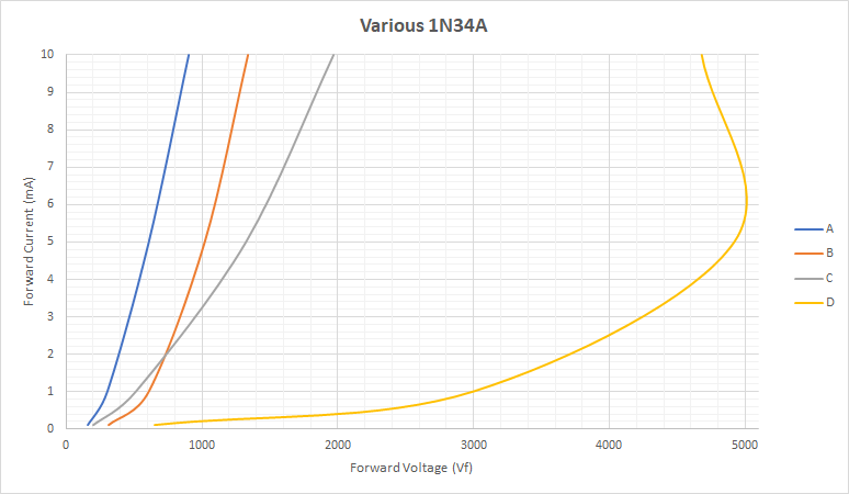
Differences between germaniums
The 1N34A used in this experiment are legit NOS germanium diodes. But what would the difference be between different 1N34A diodes from the same bag? I measured four and it’s quite scary!
VI characteristics various 1N34A diodes
Visible is how the first three (A, B & C) are quite okay. Their Vf is at the right place (100 – 200mV) and their steepness is okay, theres just a big variation in steepness. The fourth one (D) seems to be straight up faulty. So always check your NOS germaniums before you put them in a device and act as if you can really hear a difference cause it’s not the difference you’re expecting!