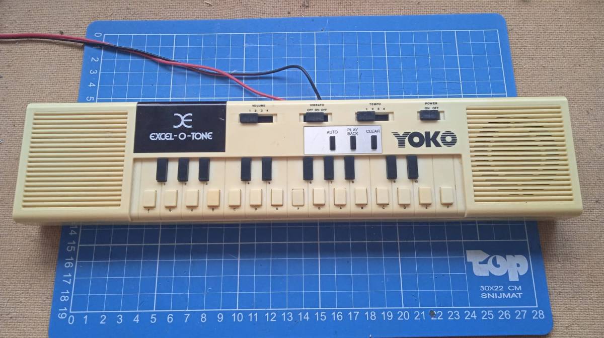
2 euros at the thriftstore, don’t mind if I do! The Excel-O-Tone is pretty much a dumbed down Casio VL-1. It makes monophonic bleep bloop noises with a parrot button that repeats your last played x amount of notes. You can add in vibrato on the bleep bloops and that’s about it. Also I haven’t got a clue what a Yoko is besides an exquisite musician and artist from Japan.
Features
Power on/off switch
25 keys
1 oscillator (monophonic)
4 volume levels
4 tempo levels
Off-On-Off vibrato function
Note sequence repeat button
No clue what the “auto” button does, it just stops all keys from making sound
Headphone output (3.5mm)
Battery powered (4x AA @ 1.5V)
2 extra spots to store batteries for your calculator or something?
DC IN (probably 6v)
Yellowed
Why it sucks
Wonky key response. Keys don’t register when playing too fast, sometimes stutter, sometimes plays an x amount of time even after letting go. Not very musician friendly so to speak.
Vibrato not very convincing, also why is that switch off-on-off?
The sequence repeat function doesn’t take rhythm in account, every note plays for the same duration.
Teardown
First thing we see are two speakers (such a luxury!) a small PCB on the bottom for the DC IN and headphones out and a big PCB on the top which has all the rest.
Zooming in on the interesting part shows us what they use for clock, microcontroller and audio output amp.
My guess is the CD4069 (Hex inverter) has some function as clock for the COP420 (datecode week 8, 1985) that happens to be a 4 bit microcontroller which also handles all the other functionality like the “keyboard” and other switches and buttons.
They chose to use an LM386 (type 1) as driver for the two speakers. Why they use two speakers is a cost-cutting mystery to me as the “synth” is mono. To make matters worse, it seemed like the speakers were connected out of phase which initially gave me acoustic headaches while playing the bleeps and bloops. I decided to swap the wires of one of the speakers to fix that.
Always interesting to see the manually routed single sided boards. If you didn’t know yet, the PCB designs were laid out with tape! This is why the tracks look so wobbly. The keys just use a membrane type-o technology. Nice and cheap. The switches are stuck on the PCB by those black plastic frames. No way to replace them if something were to happen to them!
Note the unused footprint in the top-left corner. Seems like they were also in the process of copying the calculator which could be found on the Casio VL-1.
Why do I even bother with toys you ask? Well it was cheap at the thriftstore and the keys felt very usable for other projects if the keyboard tuned out to be broken or straight up useless.
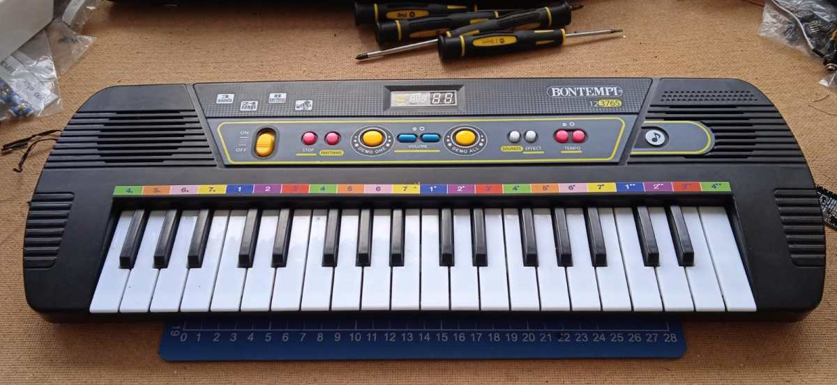
So I already featured some Bontempi on here, especially because they also made a ton of very beautiful vintage instruments but then went the cheapo children’s toy road and here we are.
The sounds are horrible, the features horrible, the thing is buggy and glitchy and indeed only children would enjoy it. It’s like a christmas card with knobs.
Features
On/Off toggle switch
3 sounds (pulse, piano(?), violin)
8 rhythms
24 songs with demo song button
Microphone input (wow!)
DC voltage input (+6VDC) or 4 AA batteries
37 keys (but there’s a catch!)
Volume control (2 stages: normal and overdrive)
Rhythm select and stop button (but there’s another catch!)
Sound effect button!
Tempo up and down buttons (more catches here…)
Why it sucks
The black keys do not work as expected. They just play the nearest white key to the right. In short, this keyboard is in C major but they even fricked that up by having the A key play a A#. Very fonky.
When you start a rhythm and want to play along, you will be disappointing. As soon as you play a note the rhythm ceases to exist.
Keyboard is monophonic but the demo songs polyphonic.
The louder volume setting quite literally overdrives the amplifier chip. Poor parents.
There are 2 tempo buttons for the rhythms but they both perform the same function: they toggle between two BPMs.
The sound effect button adds a pleasant tremolo to the pulse sound, but on the other two its for some reason 3x faster.
Keys cannot be held down, the sounds just stop playing after a second. Actually, the timing is dependable on the pitch of the note as higher notes are just the 1 second sample played faster.
Microphone input is very quiet, volume buttons have no effect on it. Obviously a poor passive mixer on the amplifier chip.
Teardown
So what makes this toy tick…
We turn the thing over and remove many many screws around the perimeter of the keyboard, and the back lifts off. Obviously, be careful as the battery terminal wires are connected to one of the PCBs.
Sooo… 1 speaker, a funny looking PCB in the top left, a loooong PCB for the keys and some flatcables going to a very specific PCB.
MQ386F-…, yeah yeah yeah, just the amplifier board. Utilizes our good friend the 386 in SMD package. Nothing else noteworthy here.
The other side, just some electrolytic and the +6VDC power and mic input. The most shocking feature of this PCB is the unused USB footprint. Did they ever plan to add USB to this? You would be surprised if I said that the enclosure actually also has an unused cutout for a USB. Would it be used for charging some lipo? to actually send midi data? to just power the thing with a phone charger? Will we ever know?
Ah the brains of the machine, SLAB-2. Yes, friends, this is just a black blob microcontroller which controls everything from button presses to sending out audio.
In closure
It is trash.
The PCB with the rubber and carbon thingies to register key presses is actually fully equipped to also register the black keys just fine, they just went cheap.
It would be fun to find out if the chip does anything with USB but as I have no clue what to connect with what, we will never know.
A two euro thriftstore find of some brandless keyboard that makes some funky noises. I can’t really put a date on it but it is probably some 90s equipment because the plastic housing is actually quite sturdy.
In the box is only the keyboard itself and a tiny paper which is supposed to function as manual, fully in German. Some genius left 4 AA batteries in there that started leaking but I won’t be using batteries anyway because this keyboard has a DC input jack for 4.5 to 6VDC. Great!
Functionality
Some specifications and stuff:
37 tiny keys, no velocity sensitivity here
4 non programmable drum pads
2 note polyphony, duophony?
8 “instruments”
8 “rhythms” (rhythmical rearrangement of the 4 drum pad sounds)
Rhythm start and stop knob
Rhythm timing LED indication
Tempo up and down control (16 levels of tempo)
Vibrato function (actually quite cool and non-intrusive)
Demo knob (Plays Greensleeves melody with whatever instrument selected)
Microphone input
Headphone output
4.5-6VDC input (center positive) or 4x AA batteries
Mono speaker to the left
Master volume stepped control
Microphone volume stepped control
On/off switch with power LED inducation
Tear it down!
It takes about 8 or so philips screws to get the back lid off. Have to be careful cause there are flimsy wires connecting the battery terminals to the keyboard… board.
So yeah, batteries on the bottom lid, speaker bolted to the left, a brown single side PCB for switches, buttons and jacks. Smaller green PCB for all the digital stuff and power amp for the speaker. Connections are made with flimsy wires and those vintage ribbon cables that barely move cause they have solid core wires inside.
Now, this board is soldered by children or something (wouldn’t be surprised), there is stray solder everywhere but I guess it passed quality control. The nice part of the PCB is that if you look carefully, there are indications of components and padnames on the PCB.
Like to the right, SP for speaker, VCC, a +6v rail and a +5v rail. And to the left some designators for the throughole components. The big star of the show, the digital chip (which has all the logic and sounds on it) is the only SMD part in the whole thing.
Due to the nature of the shitty ribbon cables it was hard to peak under the PCB where all the goodies are. To the right a giant black SMD IC I mentioned before. To the left an LM386 doing its power amplifier job. Interestingly also a trimmer potentiometer. I’m not quite sure what its job is but I assume global tuning of the instrument but I haven’t tried. The fun thing is, this whole instrument is terribly voltage controlled. Modulate the power supply and you will modulate the pitch. The circuitbending community goes wild!
A close up of the speaker side of the keyboard. 1W 8 ohms, nothing special here and on the brown PCB are some more passives doing who knows what.
I didn’t bother to get the brown PCB out, it will not be exciting at all. It will probably look very similar to the board of the Bontempi BT 805.
The incredible noise killing mod
When powered by a noisy source like a phone charger, the keyboard won’t like you. The speaker starts buzzing and just won’t shut up. Using a good PSU or a linear one fixes most of the problems. To fix it even more, I invest 2 cents by soldering a random 470µF capacitor to the +5v rail to ground. Problem solved!
Sounds!
Here is a collection of various sounds the keyboard can make, enjoy!
All 8 instruments, vibrato on, MUSIC BOX – VIOLIN – FLUTE – ORGAN – GUITAR – BANJO – HORN – PIANO
It’s noticeable how most of these “instruments” sound like retro 8 bit sounds, quite fun to play with. Violin tries the hardest to actually be a real instrument. Organ is a mystery to me what it is trying to sound like. Banjo is interesting cause it has an asynchronous tremolo going on. It is possible to trigger a note right when it is silent, which is quite annoying honestly. Piano is just a horn with a shorter decay.
“Horn”, without and with vibratoAll 8 rythms, DISCO – BALLAD – MARCH – SWING – POP – WALTZ – RHUMBA – TANGORhythms at different tempos, can get quite fonky!The 4 percussive sounds, feel free to sample, KICK – SNARE – HIHAT – “COWBELL”
The kick is just a decaying note, actually interferes a lot with bass heavy instruments like the “horn”. The cowbell is just a joke.
Greensleeves demo song featuring all instruments with no vibratoThe same but with vibrato
And to finish the article, a piece of music I created in 5 minutes by layering many of the instruments and trying to keep time with the drum pads, enjoy!
Another thriftstore find for a staggering price of €1.25! This analog style (bass)guitar tuner by Korg from the 80s works on a 9V battery and uses a switch to change which string is being tuned. It also features a function to very roughly check battery health. The tuner can use a built in microphone or a 1/4″ jack basic instrument cable to let the tuner listen to the guitar.
The GT-6J with its worn down box.
Backside with 9V battery compartment.
From the front the slide selector is visible with the 6 strings on any basic guitar to choose from.
The battery check mode makes the needle jump into the green area when the 9V battery is still good to go!
Connected my phone to it with a 440Hz test tone, it is still bang on!
Tearing it down!
To get into the tuner, only one philips head screw one the back has to be removed. The enclosure consists of two shells that are clipped together. Some gentle wiggling will make them separate.
To get a view of the component side, the panelmeter has to be desoldered from the PCB as the panelmeter is glued against the front shell.
Nice handdrawn circuit layout. Apparantly this PCB is an LM-352-A.
At the component side (from left to right) we get a view of the electret microphone, the footprint where the panel meter goes and the input circuitry for the power supply. In this case the 9V is fed to a TO-92 7805 5v linear regulator.
There are two ICs on board. An LM358 DIP-8 generic dual opamp and an MSM5208RS DIP-18 from OKI. Datecode seems to be week 19 of 1981! This IC most probably handles everything needed to compare the input signals with the reference frequencies and in turn drives the panel meter. I could not find a datasheet on this IC so if anyone finds it, be sure to message me!
The PCB also has two trimmers on board. One is accessible via the battery compartment so probably used to finetune the panel to 440Hz, either by user or factory. No clue what the function is of the other pot.
When a product proudly mentions quartz, it just means that there is a quartz crystal inside. The dimensions of the quartz crystal are defined so it resonates at a certain frequency with quite a lot of precision. This one is apparently trimmed to resonate at 5.51912MHz. You would be surprised how hard it would be to find a replacement for that frequency…
Here some more beauty shots:
Side view
Electret microphone and 5V PSU circuitry
The epicenter of tuning
A fun video where I feed the tuner a frequency modulated signal from 430 to 450Hz:
Saw this unit lying around at a thriftstore (€5) thinking it had something to do with audio because it had tape written all over it. Then I googled and found something about the Hammond XC3000? Like is it some sort of rotary speaker controller? I got excited and bought it right away to find out later it’s nothing but a so called slide dissolver.
I think the big idea is that back in the day where slide projectors were still a thing, you’d set up 2 of them and used a slide dissolver to switch between the two and make some sort of interesting audiovisual spectacle.
I don’t own any slide projectors and audio intrigues me more than video, so I might reuse the fader controller as some sort of synthesizer ribbon controller.
Anyway, I opened the thing up. It was full of CMOS logic ICs so that was a nice sight. Less nice were the amount of repairs that were done to it. I guess it wasn’t very reliable but important enough for the previous owners to replace chips capacitors and resistors all over the board. Anyway here some shots:
Excuse me for the mess. So we have a hand control input for the fader controller on top there, and a tape input I assume for… audio? The rest of the LEDs and buttons are a mystery to me. The device also uses 50 shades of DIN connectors so there’s no DC input or other simple way to turn it on.
Opening up the fader controller, we see a slide potentiometer with two end switches. I assume they allow you to go to the next slide. There’s also this blue non latching switch labeled “FLASH”. Not a single clue what that’s supposed to do but induce seizures on those watching the show.
Look at that! Quite beautiful if you ask me. Nowadays we’d use a single microcontroller to handle all of this, but back then? Digitial CMOS everywhere.
As I have no clue how this device works, can’t find any schematics or am bored enough to trace the whole machine, I’ll just leave you with a load of closeups of the board!
Another cheap thriftstore find. This 1968 cassette recorder comes with a (electret) microphone and runs on 6VDC. it also has an output for “external “SR” radio”. Whatever that may be.
It works well under low volume but at higher volume it starts squealing and with a bit of artistical input you can make it sound like a formula 1 car.
If anyone has more information or is familiar with this problem and knows a cure, don’t hesitate to leave a comment or contact me!
Front viewIn- and outputsBackside with battery compartmentView when removing the back lidClose up of the PCB
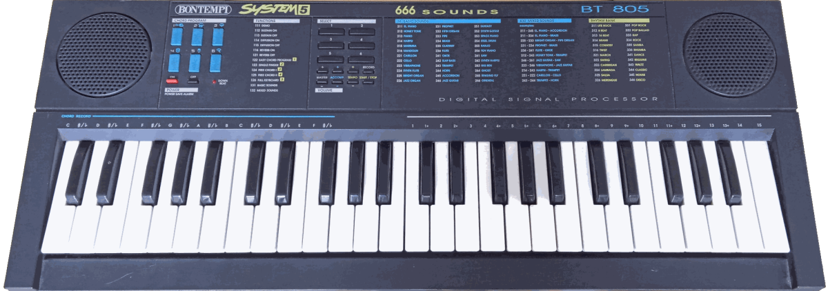
Saw this keyboard being given away for free so I decided to adopt it before it lands in the wrong hands!
On first sight it looks like the usual 90s era digital toy keyboard with cheezy sounds and rythms, and well, it is. The difference is that Bontempi used to make quite interesting organs. Nowadays they seem to be focussing on actual children’s musicial toys. I can hardly find any information on this keyboard, like date of issue or any manual at all. So I guess I’ll have to reinvent this wheel myself.
The instrument is a little scratched and I saw a lot of hairs and dust inside. Guess that’s what comes with free instruments!
Features
Hardware – 49 keys (4 octaves), no touch sensitivity or aftertouch – Limited polyphony up to 4 notes – Headphone output (1/4″ / 6.35mm jack) – Power adapter barrel jack input center positive +12v – Battery compartment (needs a lot of batteries, didn’t count) – Stereo speaker arrangement – Separate on and off buttons with audible “alarm” to notify the user if the instrument is still on after a certain time of inactivity – LED indication of “down beat” – 6 knobs for “percussion” or “chord program” – 6 knobs for the selection/programming of features – 2 volume knobs for master volume, 2 volume knobs for the accompaniment – 2 tempo knobs to set tempo – start and stop knob for demo and rythms – record knob (couldn’t find out how to use it)
Software – 36 built in sounds of which up to two can be “mixed” which leads to a total of 666 total sounds. – 24 rythms – 1 demo song – Toggle sustain on or off (similar to a sustain pedal on a piano) – Toggle diffusion on or off (literally no clue, seems to affect the stereo image) – Toggle reverb on or off (adds a bit of reverb) – “System 5” which basically means 5 different ways to play chords with the left hand.
Choosing a sound or rythm
The selection of sounds and rythms is code based. At startup electric piano (211) is selected and the lite rock (311) rythm. Pressing the start/stop button starts the rythm and the sound can be played over it.
Sound To select a different sound, simply enter the new code with the 6 select knobs. For example, pres 2-3-6 for flute. A sound of a drum will play if the entered code is valid.
Rythm To select a different rithm, also just enter the code with the select knobs. For example, 3-4-4 for classic. If there’s already a rythm playing, it will wait till the end of the bar before switching to the new chosen rythm. The tempo can be adjusted while a rythm is playing with the tempo knobs.
Mixed sounds and functions By default, the function of the keyboard is set to full keyboard (126) and basic sounds (131). To make use of mixed sounds, we first have to enter the mixed sounds function by pressing 1-3-2 on the select knobs. After that press two codes of the basic sounds in succession to have them mixed. The front panel of the keyboard shows various examples.
Demo Pressing 1-1-1 on the select knobs will automatically start the demo sequence. For some reason they thought it was a good idea to choose some funky version of the Star Wars theme for this. The tempo of the demo song can not be adjusted and loops infinitely.
System 5
Many electric organs and other keyboards have the functionality to change the leftmost keys into chord control. This means that for example just pressing the C key with the left hand, will result in a C major chord you can play over with the right hand. This keyboard decided to step it up a notch and add 5 ways to implement this chord control.
I could hardly figure out how it works so that means I just need to play around with it some more. I found that one of the systems kills the leftmost octave while turning the percussion knobs in arbitrary chords in the key of C. Another system 5 option makes it so you need to use at least two fingers to hear a chord. How to build these chords, I don’t know.
There also seem to be a way to reassign the chords that get audible via the percussion knobs, but I haven’t figured out yet how to do this.
To escape the odd chord control system 5 when you get desperate and confused, just press 1-2-6 to get the full keyboard back.
Playability
The keys feel a bit cheap and the selection knobs sometimes register twice or keep getting stuck under the panel because it’s all built on the cheap. But besides that it’s a fun instrument to play. Some sounds are straight up garbage while others, mainly the synth ones, are quite pleasing!
The percussion sounds hidden under the 6 blue percussion knobs are trash and for some reason those used for the rythm tracks sound better. Seems like they cut some features that are built into the software but are just not accessible to the user. This isn’t rare or anything, happens all the time in these kinds of devices.
One very odd thing is how the stereo image is created. The percussion sounds come from the left speaker only but when awkwardly trying to play these sound polyphonic, the keyboard sometimes decides to pass one to the right speaker. This isn’t a loose solder contact or anything, just how the thing works.
This becomes more apparent when playing the keyboard keys. The keyboard just randomly decides to send some notes to the left speaker, and others to the right and there’s nothing you can do about it. I thought the “diffusion” control would get rid of this but all that seems to do is emphasize the effect. I mean sure, it gives some sort of funky stereo image but it’s really not desired at all times. For example, when trying to record with a mono 1/4″ cable.
Teardown
Ofcourse, I am wondering what’s happening under the hood. So I decided to screw it open and check! I apologize dearly for the amount of dust and hair in the thing, I didn’t bother to clean it up before taking pictures.
Insides of the Bontempi BT 805
The keyboard consists of two single sided PCBs. One of them for the keys, and the other one for the power, amplifier, knobs and digital circuitry.
The construction for the keys actually looks quite decent. Each key has a spring and uses the usual membrane contacts to register key presses.
Close up of a part of the keyboard
Seems like each key is marked and has their own diode (1N4148), probably arranged in a way so combinations of keys dont accidentally trigger keys that aren’t pressed. They also did a bad job of cutting the strip of membrane contacts, I got 1.5 for free!
Close up of the amplifier IC
There are only two ICs on the board and one of them is this DIP-16 stereo amplifier (TEA2025B). The backside of the keyboard says that the whole system is rated for 2W and I suppose most of those watts go to the amplifier. The amplifier drives two speakers of 4 ohms and 5 watt.
Left speaker
Right speaker
Notice how these two speakers are of the same impedance and power but are physically different!
Audio amplifier IC with power input and headphones jack
In the picture above is the audio amplifier visible with the barrel jack input and the headphone jack output. Theres some ferrite (L1, L2, L3) to filter the power lines of high frequency noise. The green connector J4 is used to bring power to the keyboard PCB. The used components are all quite “modern”.
Transistor circuitry
When travelling further down the line, we come across some transistors (C33725). Luckily there are very nice markings of the components places on the component side of the PCB. This is probably the lower voltage regulator for the digital portion of the circuit were moving next.
Digital circuitry component side
J3 is the connector that comes from the keyboard PCB. On top are some of the switch contacts visible, or at least, the ones that are on the solder side.
In the topright is the connection for the 3mm LED (D1) that indicates when a rythm is on a “down beat”.
There are many links / wire bridges marked with a W which aids the single sided infrastructure.
Those black caterpillars are resistor arrays or resistor networks. Basically many resistors of the same value in one neat package.
Q21 (the blue dot on the right) is possibly a crystal resonator. The heart of the microcontroller I’ll show next.
The central microcontroller / processor
An untracable microcontroller / processor from Texas Instruments. Here are all the samples, sounds, rythms and logic stored.
Audio demos
The Star Wars theme:
Star Wars demo sequence
Demo #1, saw patch:
Processed demo #1Raw demo #1
Demo #2, a tubular bells adaption
Processed demo #2 (a tubular bells adaption)Raw demo #2
Demo #3, melody over a rythm
Processed demo #3 (includes a rythm)Raw demo #3
Demo #4, the percussive sounds in no particular order
While trying to get a versatile LFO going and failing at it… I decided to already go a step further and take a look at attenuverters.
Attenuverters
The concept is easy. With the potentiometer set at 12 o’clock, we get no signal from the input at the output. When rotating the potentiometer to the right, we slowly get our input signal back. Once we reached the limit of the potentiometer, the full input signal is at the output. Important: between 12 o’clock and the mostright limit is an attenuated version of the input signal!
Now if we rotate from 12 o’clock to the left, the same effect happens BUT the signal is inverted! So a sawtooth can be shaped into a ramp and an ADSR can be shaped from a pluck to a sidechain compression effect!
The effect of attenuverting at different potentiometer positions. The rightmost signal was originally at the input.
Offset
Offsetting a signal is the act of adding or subtracting the DC level. This basically just means shifting the whole signal up or down.
This can be very useful to for example set a base control voltage where let’s say, a LFO will swing around. An simple practical patch is to route a 5Hz sinewave (or triangle…) to the input of the attenuverter, then routing the output to a VCO. Now dial in the desired frequency / tone with the offset knob and use the attenuverter control to dial in a slight vibrato!
The effect of offsetting at different potentiometer positions. The middle position is equal to no added offset.
Gain
Now you might think, where do you need gain for? Many attenuverter modules only offer an attenuvert and offset control. Well imagine that your ADSR or LFO has a poor output swing or just doesn’t have the voltage range it needs to? This can be easily solved with a bit of gain!
In my design I don’t have variable or user accessible gain control. I did this on purpose because the attenuvert control will practically control the overal gain. So having the attenuvert potentiometer all the way to the right, won’t give the original input signal, but an amplified version!
This extra gain does make the attenuvert control more sensitive. Tuning in for example a subtle vibrato will not need a lot of travel on the potentiometer, but it surely isn’t impossible to tune in.
The design
Having attenuverting, offsetting and a higher than unity gain makes this design an extremely versatile tool in any synth setup.
Attenuvert and offset and gain schematic
Opamp U1A is the basic attenuverter design. Really nothing special to see here. The big idea is that RV1, depending on potentiometer position, can change the configuration of the opamp from non-inverting to inverting. Hence it does attenuverting. R1 and R2 are optional resistors you can place to make the attenuvert control less finicky around 12 o’clock. I had good results with anything between 10k and 47k but just see for yourself what feels good.
The practice of putting resistors around a potentiometer is called tapering: changing the response of a potentiometer. If you need a bit more precision in the first 40% of a potentiometer or if you need to limit the range of your potentiometer, tapering will often get you very far. And it's cheaper than buying a dedicated potentiometer for it! The internet has enough guides on how to taper a potentiometer to your needs, so try that first before investing in that weird expensive pot!
After attenuvertion the signal is passed on to an inverting amplifier with a gain of x10 due to R7 and R5. A DC offset is injected onto the opamp summing point thanks to R11 and potentiometer RV3. C3 is an optional capacitor to bandwidth limit the opamp to about 20kHz if you so desire. R15 is an optional resistor that limits the drive current of U1B in an output short circuit event.
Scope captures
To show that the schematic actually also works in the real world, I built it up on breadboard and took some scope captures showing the basic functionalities.
The output waveform of a sawtooth generated by a phone cause I lack a proper sawtooth LFO. It is kinda hard to show inversion on a sinewave, squarewave or triangle because of their symmetry, hence I went with the janky sawtooth at a frequency quite higher than the LFO domain. It doesn’t matter as it will still show just fine how the attenuverter works.
In this one the attenuverter potentiometer is rotated the other way around, resulting in an inverted sawtooth -> a ramp.
Here I added some DC offset action which shifts the whole waveform above 0v for VCO or other CV input modules that can’t cope with negative voltages.
When you get into synthesizers (or any other analog audio related topic), you quite quickly come across designs like VCAs with long tailed pair (LTP) input stages or the famous ladder filters that require you to have so called “matched” transistors. Transistors are usually quite variable (just measure some Hfe (beta) of some to find out), but less variable than lets say, JFETS. Still for these applications you need to find pairs that will somewhat behave the same.
So I looked in my BJT drawer and found a nice bag of 2N3904 NPN bipolar transistors I bought years ago from good ol’ China. The bad thing is that these might not even be 2N3904 transistors, the good thing is that they behave like general purpose transistors for the past few years.
So I randomly took 20 of them out the bag and decided to see how the matching procedure is like. The first test setup I found was “apparantly” used by Moog to find matches. Well, that gotto go right, right?
Ofcourse I used the one for the NPN transistor. I didn’t really care much for the precision of the used resistors and tried to get the power supply as close as possible to +-10v. I ended up with a stable current of 106µA, guess that is close enough!
Ofcourse don’t handle the transistors with your fingers and give them some time to get to ambient temperature. Transistor parameters are heavily temperature dependent (also one of the reason we try to match them).
Moving the test leads from one transistor to the other is safer than moving the transistors to the test leads. All just to make sure they stay at ambient temperature.
So I measured the Vbe of the 20 transistors and wrote the voltage down in millivolts (mV):
Alright, they’re all already fairly close it seems. Maybe a bit too close…
I got sceptical so wanted to retry the test with another multimeter (the one I used first is a no brand China one that usually doesn’t betray me…). So I grouped the 20 transistors per value as in the picture above.
Then did the measurement again, but with the other multimeter. Suddenly all values were a steady 30mV higher. Now that is nightmare fuel!
The “big” number is the millivolts the transistors gave me with the cheapo meter. Now it seems like each transistor gave another spread for every group. Seems more realistic, so I got hope again. But this is not where I wanted to stop.
I decided to group the ones that match again, and let them fight in a transistor battle to death.
Basically I used another test setup that lets you test and compare two transistors at once…
Nothing much to see here, it’s just important to get stable power supply rails and match the 100k resistors to be decently matched. This should be rather easy in 2021. D1 was in my case just a general purpose 1N4148.
If the transistors are perfectly matched, the voltage from emitter to emitter should be 0V. If the transistors are unmatched, a voltage difference will build up and be visible on the multimeter.
Visible is what the difference in voltage was that showed up on the multimeter. Must say it is quite impressive and immediatly turned on my scepticism again.
Ofcourse it might’ve been better to get a multimeter that could measure smaller than 1mV steps (with an unknown precision, didn’t bother to check it), but if the results are already this small (the Moog test setup has matches pass at +-2mV differences!) I am not sure how a more precise multimeter will even matter.
Is matching of transistors something we should care about in 2021? Do Chinese mystery transistors come matched off of the boat? Am I happy with the results?
All questions I don’t quite have an answer on. But for now, bag it and tag it!