SWEEX 7.1 External USB Sound Card

The thriftstore I often visit received a big load of 00s electronics. Some more useless than others. A 7.1 external USB sound card grabbed my attention as it used to be a much used device and cost nearly nothing. So I grabbed it.

Sadly, this device is so outdated (2009) that I had a hard time getting drivers to work under Windows 10 so I just gave up on it as I didn’t even have a usecase for it. So I decided to open it up and see what makes it tick.

Features

  • Two microphone inputs
  • Headphones output
  • Line-in
  • Front, surround, center/bass and back outputs
  • S/PDIF
  • Knobs for volume + and -, mic mute and mic volume.

Teardown

Overview

Torn down it actually looks like a sleek design and a funny small device.

The sound card is controlled mainly by one IC.

CM6206 does it all.

CM6206 block diagram

Bontempi 123765 Keyboard

Why do I even bother with toys you ask? Well it was cheap at the thriftstore and the keys felt very usable for other projects if the keyboard tuned out to be broken or straight up useless.

So I already featured some Bontempi on here, especially because they also made a ton of very beautiful vintage instruments but then went the cheapo children’s toy road and here we are.

The sounds are horrible, the features horrible, the thing is buggy and glitchy and indeed only children would enjoy it. It’s like a christmas card with knobs.

Features

  • On/Off toggle switch
  • 3 sounds (pulse, piano(?), violin)
  • 8 rhythms
  • 24 songs with demo song button
  • Microphone input (wow!)
  • DC voltage input (+6VDC) or 4 AA batteries
  • 37 keys (but there’s a catch!)
  • Volume control (2 stages: normal and overdrive)
  • Rhythm select and stop button (but there’s another catch!)
  • Sound effect button!
  • Tempo up and down buttons (more catches here…)

Why it sucks

  1. The black keys do not work as expected. They just play the nearest white key to the right. In short, this keyboard is in C major but they even fricked that up by having the A key play a A#. Very fonky.
  2. When you start a rhythm and want to play along, you will be disappointing. As soon as you play a note the rhythm ceases to exist.
  3. Keyboard is monophonic but the demo songs polyphonic.
  4. The louder volume setting quite literally overdrives the amplifier chip. Poor parents.
  5. There are 2 tempo buttons for the rhythms but they both perform the same function: they toggle between two BPMs.
  6. The sound effect button adds a pleasant tremolo to the pulse sound, but on the other two its for some reason 3x faster.
  7. Keys cannot be held down, the sounds just stop playing after a second. Actually, the timing is dependable on the pitch of the note as higher notes are just the 1 second sample played faster.
  8. Microphone input is very quiet, volume buttons have no effect on it. Obviously a poor passive mixer on the amplifier chip.

Teardown

So what makes this toy tick…

We turn the thing over and remove many many screws around the perimeter of the keyboard, and the back lifts off. Obviously, be careful as the battery terminal wires are connected to one of the PCBs.

Sooo… 1 speaker, a funny looking PCB in the top left, a loooong PCB for the keys and some flatcables going to a very specific PCB.

MQ386F-…, yeah yeah yeah, just the amplifier board. Utilizes our good friend the 386 in SMD package. Nothing else noteworthy here.

The other side, just some electrolytic and the +6VDC power and mic input. The most shocking feature of this PCB is the unused USB footprint. Did they ever plan to add USB to this? You would be surprised if I said that the enclosure actually also has an unused cutout for a USB. Would it be used for charging some lipo? to actually send midi data? to just power the thing with a phone charger? Will we ever know?

Ah the brains of the machine, SLAB-2. Yes, friends, this is just a black blob microcontroller which controls everything from button presses to sending out audio.

In closure

It is trash.

The PCB with the rubber and carbon thingies to register key presses is actually fully equipped to also register the black keys just fine, they just went cheap.

It would be fun to find out if the chip does anything with USB but as I have no clue what to connect with what, we will never know.

Portable Electronic Keyboard

Full album made with the sounds of this keyboard!

A two euro thriftstore find of some brandless keyboard that makes some funky noises. I can’t really put a date on it but it is probably some 90s equipment because the plastic housing is actually quite sturdy.

In the box is only the keyboard itself and a tiny paper which is supposed to function as manual, fully in German. Some genius left 4 AA batteries in there that started leaking but I won’t be using batteries anyway because this keyboard has a DC input jack for 4.5 to 6VDC. Great!

Functionality

Some specifications and stuff:

  • 37 tiny keys, no velocity sensitivity here
  • 4 non programmable drum pads
  • 2 note polyphony, duophony?
  • 8 “instruments”
  • 8 “rhythms” (rhythmical rearrangement of the 4 drum pad sounds)
  • Rhythm start and stop knob
  • Rhythm timing LED indication
  • Tempo up and down control (16 levels of tempo)
  • Vibrato function (actually quite cool and non-intrusive)
  • Demo knob (Plays Greensleeves melody with whatever instrument selected)
  • Microphone input
  • Headphone output
  • 4.5-6VDC input (center positive) or 4x AA batteries
  • Mono speaker to the left
  • Master volume stepped control
  • Microphone volume stepped control
  • On/off switch with power LED inducation

Tear it down!

It takes about 8 or so philips screws to get the back lid off. Have to be careful cause there are flimsy wires connecting the battery terminals to the keyboard… board.

So yeah, batteries on the bottom lid, speaker bolted to the left, a brown single side PCB for switches, buttons and jacks. Smaller green PCB for all the digital stuff and power amp for the speaker. Connections are made with flimsy wires and those vintage ribbon cables that barely move cause they have solid core wires inside.

Now, this board is soldered by children or something (wouldn’t be surprised), there is stray solder everywhere but I guess it passed quality control. The nice part of the PCB is that if you look carefully, there are indications of components and padnames on the PCB.

Like to the right, SP for speaker, VCC, a +6v rail and a +5v rail. And to the left some designators for the throughole components. The big star of the show, the digital chip (which has all the logic and sounds on it) is the only SMD part in the whole thing.

Due to the nature of the shitty ribbon cables it was hard to peak under the PCB where all the goodies are. To the right a giant black SMD IC I mentioned before. To the left an LM386 doing its power amplifier job. Interestingly also a trimmer potentiometer. I’m not quite sure what its job is but I assume global tuning of the instrument but I haven’t tried. The fun thing is, this whole instrument is terribly voltage controlled. Modulate the power supply and you will modulate the pitch. The circuitbending community goes wild!

A close up of the speaker side of the keyboard. 1W 8 ohms, nothing special here and on the brown PCB are some more passives doing who knows what.

I didn’t bother to get the brown PCB out, it will not be exciting at all. It will probably look very similar to the board of the Bontempi BT 805.

The incredible noise killing mod

When powered by a noisy source like a phone charger, the keyboard won’t like you. The speaker starts buzzing and just won’t shut up. Using a good PSU or a linear one fixes most of the problems. To fix it even more, I invest 2 cents by soldering a random 470µF capacitor to the +5v rail to ground. Problem solved!

Sounds!

Here is a collection of various sounds the keyboard can make, enjoy!

All 8 instruments, vibrato on, MUSIC BOX – VIOLIN – FLUTE – ORGAN – GUITAR – BANJO – HORN – PIANO

It’s noticeable how most of these “instruments” sound like retro 8 bit sounds, quite fun to play with. Violin tries the hardest to actually be a real instrument. Organ is a mystery to me what it is trying to sound like. Banjo is interesting cause it has an asynchronous tremolo going on. It is possible to trigger a note right when it is silent, which is quite annoying honestly. Piano is just a horn with a shorter decay.

“Horn”, without and with vibrato

All 8 rythms, DISCO – BALLAD – MARCH – SWING – POP – WALTZ – RHUMBA – TANGO

Rhythms at different tempos, can get quite fonky!

The 4 percussive sounds, feel free to sample, KICK – SNARE – HIHAT – “COWBELL”

The kick is just a decaying note, actually interferes a lot with bass heavy instruments like the “horn”. The cowbell is just a joke.

Greensleeves demo song featuring all instruments with no vibrato

The same but with vibrato

And to finish the article, a piece of music I created in 5 minutes by layering many of the instruments and trying to keep time with the drum pads, enjoy!

Sanyo M-787AZ Cassette Recorder

More thrifting. Probably early 70s. Has a battery, DC and AC input which is nice to have. Big volume knob and various interfaces for headphones, microphones and radio.

Front view
Interface of connectors and volume
Backside
View when removing the back lid
I had to desolder or snip some wires to get the board out but I didn’t want to get that far, so this is the best I could do.
PCB sideview
Two transistors in a custom heatsink bolted onto the side
2SB22 SANYO transistor

VCO 4069 Build Report

Introduction

During the synthesizer building journey, I was looking for a VCO with a V/OCT control voltage input. Quite quickly I stumble upon the designs by René Schmitz. My eye fell on a VCO that utilizes a 4069 hex interver IC. I have quite some of those laying around, and as the design doesn’t use any other exotic components, I decided to give it a go.

The design

I drew the schematic in Kicad so I could later on turn it easily into a perfboard layout.

I changed a few things but not much:

  • The pots were 22k which to me just sounds odd. I lowered them to a more commonly available 20k.
  • Output caps for the waveforms are way higher. Not for a particular reason. I just own a lot of 10µF capacitors.

The design also shows the usage of 10k thermistors (NTC). I sourced mine from China as I wasn’t in the mood to pay good bucks for “special synthesizer approved” thermistors. I’ve yet to find out if they really play that much of a role in this design or could’ve easily been omitted.

Perfboard layout

After laying out the schematic, I translate all the components to footprints that all obey a 0.1″ or 2.54mm pinspacing. Depending on the space and efficiency, I have resistors and diodes that “stand upright” so they only cover 2 pads, instead of 4.

The base layout is copied from Schmitz, with some alterations here and there. Green connections pretty much mean a jumper wire.

As you can see, in the upper left corner of the board is the exponential converter. Because I used a 2N3904 and 2N3906, they aren’t facing eachother. This might have an impact on the temperature stability. My guess is that I can easily replace them with transistor types with mirrored pinouts, so I can just have them face to face and glue them down.

Those with a keen eye will see that the potentiometers are missing. That’s right. I usually treat them as an afterthought to be solved by jumperwires.

Perfboard / protoboard

With the layout done, it was time to transfer it to protoboard. I’ve yet to find out if I love or hate protoboard. I find it often to be a miserably tiresome way to get your electronics projects going. Sadly PCBs will cost more money (not a lot, but still more money) and vero or stripboard just makes me puke.

Tuning

Yes this design isn’t very temperature stable, and I also didn’t try my best to make it better. During the tuning process I did tie the two transistors together so their enclosures touch. But even thinking about a holiday is Spain makes them drift a few cents.

Anyway, this was the first time I tried tuning a VCO and had no clue what the procedure was. So I just did what seemed logical. I set the 1k trimmer pot about halfway, the external CV source on 1VDC and tuned the output with the CV pot to be about 200Hz. I was quite sceptical of my approach so I didn’t bother going for precision or a logical starting frequency. I just wanted to confirm my approach.

With 1V being about 200Hz, I started setting the CV to 2V, then 3V, … 5V. 5 octaves should be quite enough, right? Every time the frequency was off, I adjusted it with the trimpot. Then went down again, and up, until I was quite satisfied with the tuning. One value I missed was 0V, so I slammed down the CV and saw the frequency going beautifully to somewhere quite close to 100Hz.

I noted the sweep in a graph, voltage on the X axis and frequency on the Y:

I guess for a more musical approach, one should take a bit more time and care in the tuning process and get it close to bang on. But this graph already tells me that there is a lot of potential in this VCO.

Waveforms

Here are some quick and dirty images of the waveforms:

Squarewave / pulse @ 50% PW, 400Hz (Clipping the audio interface input, oops!)
Squarewave / pulse @ not 50% PW, 400Hz (Also clipping the audio interface…)
Sawtooth @ 400Hz

Audio demo

Full CV sweep

Waveforms and PWM

Downloads

Kicad (5.1.9) project

Lunetta: LM7805 Power Supply

Maybe you’ve seen the YouTube video in which I design a steady 5VDC power supply with the LM7805. I left many details and design decisions behind to have a more straight to the point video. In this post I will go into more detail on each design decision made.

fullschem

The LM7805 and input voltage

The LM7805 is a linear regulator with a fixed voltage output. Linear regulation means that a voltage higher than the fixed output voltage is attached to the input of the regulator, and the regulator will waste electrical energy in the form of heat, until the output is at the required voltage. This is terribly inefficient but when the input voltage is kept as low as possible, losses are minimized.

The datasheet of the LM7805 tells us that we need at least 7VDC at the input to get a 5VDC output voltage. But because 7V powr supplies aren’t that common, it’s better to choose the next common voltage source which is a 9V battery.

datasheet2

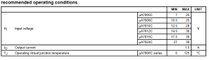
If you can get your hands on a mains adapter from 7VDC to 12VDC, you will be fine too. I set the max at 12V because otherwise you will get too far from the 7V minimum, resulting in the regulator heating up too much.

If you only have a voltage source higher than 12V, I highly recommend to first use a TO-220 package 7805, and attach a heatsink to it.

Decoupling capacitors and ripple

Working principle

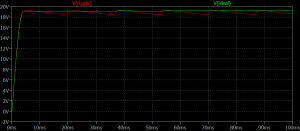
To make sure the regulator is stable (= 5V output without ripple or oscillation), decoupling capacitors are added to both the input and output of the regulator. These capacitors can be seen as small local batteries that are really good at being charged and discharged. This property is very important when for example the voltage regulator or the circuitry we’re going to power is suddenly in a high demand of power. Instead of sourcing it aaaall the way through cables etc at the voltage source, it can just use these little ideal batteries.

Capacitor values

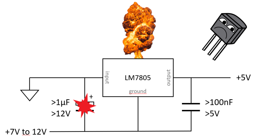
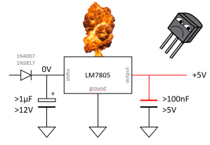
We don’t really calculate the values of these capacitors cause it’s not an exact science. The biggest rule of thumb is that the input cap is bigger than the output cap. And when we’re talking about “decoupling” and “small”, a cap of 100nF is what we need. So it’s always good to stock up on 100nF ceramic capacitors for this job.

The input capacitor can for a rule of thumb be 10x or more bigger. So 1µF electrolytic will suffice. But this shouldnt be the standard because decoupling capacitors also have the great property to filter out ripple on the power supply.

Nasty input ripple filtering

We want an as flat as possible DC voltage to power our electronics. The moment small bits of AC or ripple is present in this DC, it’s not clean anymore and it will affect the performance of the circuitry.

To filter out this nasty AC, we use capacitors to short them to ground (because AC thinks capacitors are just wires). The nastier the AC is (= big amplitude), the heavier the decoupling has to be. Note that we’re now focussing on the input decoupling of the 7805. This is only interesting when the 7805 is fed by a mains adapter because they tend to have small amounts of ripple. This can be your typical 50/60 100/120Hz ripple, or a few kilohertz when the mains adapter uses switching technology.

The more filtering is needed, the bigger capacitors are used. So don’t be afraid if you need a 100µF electrolytic capacitor at the input, cause it is also very common.

ripple

Luckily the LM7805 also has something called ripple rejection. This means that the regulator itself will also do its best to filter ripple from the input voltage, and not have it appear at the regulated output voltage.

Nasty output ripple filtering

So now you might think, we filtered the input voltage enough and the regulator helps us too -> The output voltage must be as clean as it gets now! Yes, this is very true. The output voltage is extremely clean now, but sadly it will get dirty as soon as we start powering CMOS chips with them.

Why? Because we’re going to create lots of squarewaves and they are nothing but switching transistors. This switching will have an effect on the power supply because the demand of current keeps changing very fast. So while we produce our funky sounding squarewaves, the 5V power rail will get messed up with ripple.

This is why the output of the regulator also needs a capacitor and another rule of thumb is to have each CMOS chip have its own 100nF capacitor too. This can count up to many 100nF scattered around the circuitry because we’ll have so many CMOS chips to decouple. And that’s totally fine and is very common in both amateur and commercial electronics design.

A reminder for the type of capacitor: For low values like the 100nF capacitors, use ceramic or film capacitors. For values higher than that, use electrolytic capacitors.

A last note and warning: check the voltage ratings of the capacitors! The input capacitors need to be rated higher than the voltage of the mains adapter or battery. To be safe, you want to have a nice margin. So when using a 9V battery, get 15V capacitors and when you use a 12V DC supply, get 15V or higher rated capacitors. Not respecting the voltage ratings of capacitors will lead to unsafe conditions. The output capacitors have to be rated at 5V or higher. Most capacitors will be far higher rated than that but still check it to not get exploding surprises.

Protection against reversed voltages

Input protection

What if we connect the battery the wrong way around, or plug in a mains adapter with a reversed voltage? First of all the input capacitors are electrolytic and polarized. They will heat up or explode. Second of all, the LM7805 might die too soon after. Reverse polarity is a bitch but the protection is simple.

explosions

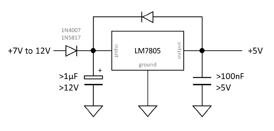
Just put a diode in series with the power supply, pointing towards the input of the voltage regulator. Also place it before the decoupling capacitors because we want to protect them too. When the polarity is right, the diode will just allow current to flow and everything is fine. When the polarity is reversed, the diode will block all current and nothing will be powered or explode.

inputprotection

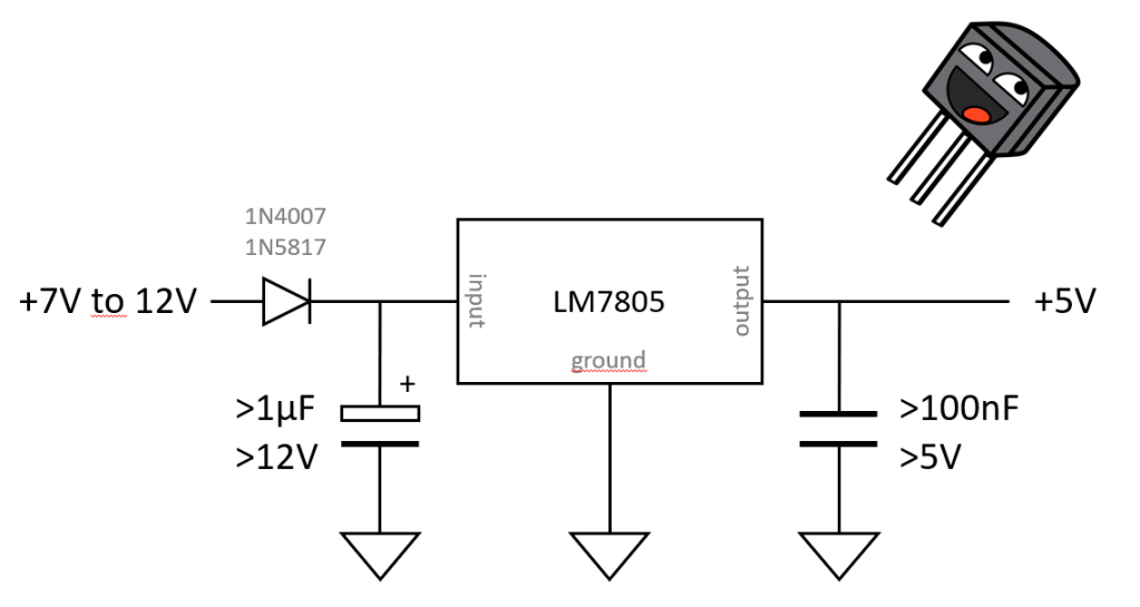
The only downside to this protection is the small voltage drop across the diode. So if we have a 9V battery and a general purpose rectifier diode like the 1N4007, we will have a voltage of 8.3V at the other side of the diode (assuming a forward voltage Vf of 0.7V). This might not be much of a problem because 8.3 is still above the minimum of 7V, but we can do better. If we use a schottky diode like one from the 1N58XX series, we suddenly lower this voltage drop to about 0.3V. This has two benefits.

One, theres less of a voltage drop, so more voltage to work with. Two, the diode has less power to dissipate as the formula is P = Vf * I. But we won’t be pulling that much current that the diode might faint so it will be fine.

Output protection

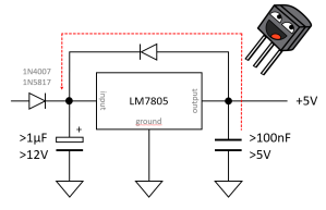
There is a rare case where the output voltage of the regulator can be higher than the input voltage. For example because theres no voltage source connected at the input but the output capacitors are all still charged to 5V. This condition can damage the regulator.

outputtoohigh

To fix this, we add another diode (can be a 1N58XX schottky too) from the output of the regulator to the input. This way the capacitors all have a way to safely discharge when this scenario occurs and the regulator is safed.

fixedoutputtoohigh

Extra stuff and calculations

Power dissipation

Power dissipation of linear voltage regulator consists of two parts: The power dissipation because of the current demand of the circuitry (load) that’s going to be powered by the voltage regulator, and the power dissipation by the regulator itself due to bias current.

Ptotal = Pload + Pbias

Pload = (Vin – Vout) * Iload

Pbias = Vin * Ibias

P = (Vin – Vout) * Iload + Vin * Ibias

Often the power dissipation of the biasing circuitry is much smaller than the power dissipation caused by the load. In such cases Pbias can be omitted from the calculation.

Example:

We have an LM7805 with an input voltage of 9V, and the load pulls a constant current of 100mA. Calculate the total power dissipation of the linear regulator.

Variables:

Vin = 9V
Vout = 5V
Iload = 100mA
Ibias = 4.2mA (datasheet!)

P = (Vin – Vout) * Iload + Vin * Ibias

= (9 – 5) * 0.1 + 9 * 0.0042 = 0.4378W

So the package will have to dissipate a little less than half a watt which is fine for a TO-220 package without heatsink.

The power dissipation due to the biascurrent of the regulator is about 8.6% of the total power dissipation. This is small but still something to keep in mind.