

Me and Dylan and David from the DIY guitar pedal/effects community decided to see for ourselves what the fuzz is about regarding diodes and their “softness”. Why do people like germaniums over silicons? What is the effect of multiple diodes in series? How exactly does the PN junction of a MOSFET look like? All these questions and more will be answered.
Test setup

Tools and equipment:
– Two multimeters (Voltage and current (mA))
– Stopper resistor (100 – 1k)
– Variable resistor (100k)
– PSU (9V battery or lab PSU 0-20V (RECOMMENDED))
– Breadboard + jumperwires and crocodile clips (RECOMMENDED)
By varying the power supply or RV1 it is possible to alter the current through the DUT (Diode Under Test). We measured and noted the voltage across the diode at 4 points: 0.1mA, 1mA, 5mA & 10mA.
For more precision measure 3 or more of the same diode type and average the results.
Overview
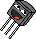
In the following image are all diodes visible we have tested. These are various general purpose silicon, germanium, zener and other semiconductors (Click for bigger image!).
In the remainder of this post the curves will be grouped and interesting relations will be further elaborated.
(Fake) Germaniums and Schottkys
We know that germanium and schottky diodes are characterized by having a very low Vf of around 100-200mV. What makes germaniums so much more interesting than silicons is that they are very soft at clipping which to some guitarists create audible differences to their tone. This is visible in the graph by the steepness of the curves.

If you are not sure if your diode is really a germanium or just a schottky, you can do the test as described above and find out! This way we found out some unmarked diodes (Ge 1 through 4) were germaniums and more importantly, 1N34A diodes advertised on Ebay as “germanium” were just 1N60 schottkys with their markings rubbed off! This is why you cannot judge a germanium on just their Vf!
Another interesting relation is how a BAT41 silicon schottky diodes has similar steepness as germanium diodes and could be used as germanium replacement.
When combining diodes you can get some very interesting results. Two 1N34A germaniums in series result double the Vf but also less steepness which results in the equivalent diode being even softer. If you want best of both worlds (High Vf thus high output signal and softness) you can put a silicon in series with a germanium.
Silicon
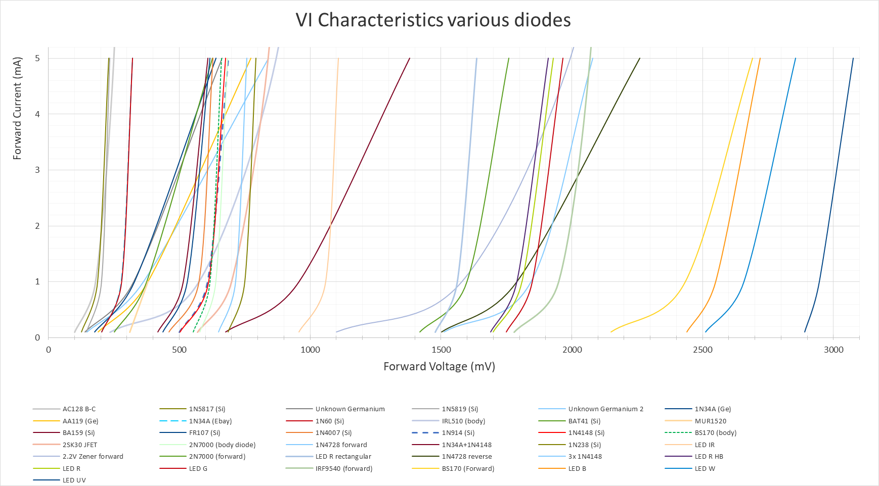
This very happy and colorful graph shows all the silicon diodes we measured.
Note how silicons have a rather steep curve and the schottky diodes (1N5817, 1N5819, 1N60 & BAT41) have a very low forward voltage. The BAT41 once again shows that it might as well be regarded as a germanium diode with its softness. I’d also like to take a moment to note that 1N4148 silicon diodes are the same as 1N914 silicon diodes.
Zener
Zener diodes can be used in two ways: reverse and forward bias. The forward bias will result in a regular forward voltage of a silicon diode but the reverse bias will result in a curve that slowly reaches the zener voltage. The higher the rated zener voltage, the less current is needed to reach it.

In the above graph a regular 1N4148 silicon diode is used as reference. It is visible that zener diodes in reverse bias are rather softish but we also needed quite a lot of current before they eventually reached their zener voltage (outside the graph). There are two types of 1N4728 tested. These are 3.3V zener diodes (at 70mA…) of which one legit kind eventually reached 3.3V but the faulty chinese ones reached 4.3V at 100mA! This way I found out that I bought faulty zeners a few years back!
Note that one zener diode can theorethically be used to clip both sides of the waveform, one at the forward bias voltage and one at the reverse bias voltage (zener voltage).
Light Emitting Diodes (LEDs)
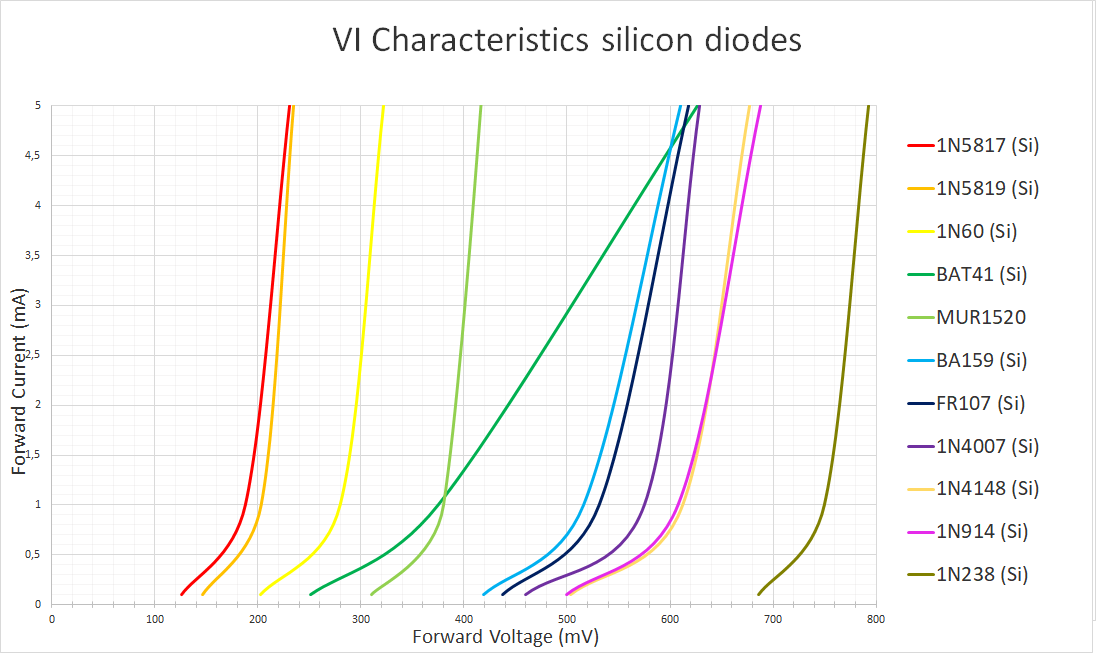
Also LEDs are beloved in the guitar pedal community as they allow plenty of headroom and clip hard. Sometimes they even light up when theyre being drive hard enough!
Because the color of an LED is controlled by the band gap of the PN junction, it’s logical that the forward voltage is analoguous to the spectrum of the visible light. Funfact: there is a good chance all diodes are LEDs, many just dont emit photons with a wavelength we can see!
Using LEDs as clippers is really a matter of taste and how much output volume/headroom you want.
MOSFET and JFET
Some pedalbuilders thought it was an interesting idea to use PN junctions inside of FETs as clippers. This is because they tend to be a little softer than a regular silicon diode.

When using the body diode of the FETs it is visible that they pretty much behave like a regular silicon diode like the 1N4148. Using the forward biased PN junction of these FETs result in less steep curves. Use the 1N34A germanium diode and 1N4148 silicon diode as reference for the FET curves.
Let’s put them in series!
As already briefly discussed at the germanium diodes, it is a common practice to put multiple diodes in series to alter the forward voltage and softness of the equivalent diode.
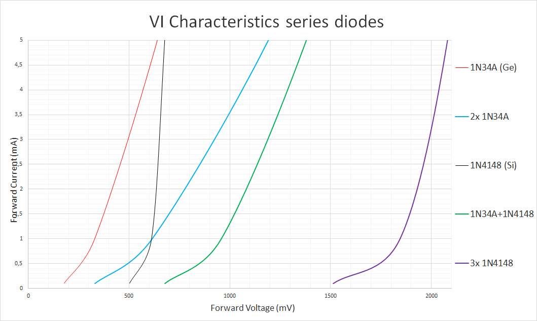
Using the 1N34A (Ge) and 1N4148 (Si) as referencee it is visible what the effect is of putting diodes in series. Ofcourse many more combinations are possible: Zeners with germanium, LEDs with schottkys, Silicons with FETs but we just took a few to prove the point of putting diodes in series.
Putting germaniums in series doubles the Vf and makes the curvature less steep. Putting a silicon in series with a germanium results in an addition of Vf and the steepness will be the best of both worlds. Putting many silicons in series will weaken the curvature more and more but in turn also grants a high Vf.
In theory you could put about 8 germanium diodes in series to create the headroom of a red LED but with an extreme softness almost comparable to tube distortion.
Differences between germaniums
The 1N34A used in this experiment are legit NOS germanium diodes. But what would the difference be between different 1N34A diodes from the same bag? I measured four and it’s quite scary!

Visible is how the first three (A, B & C) are quite okay. Their Vf is at the right place (100 – 200mV) and their steepness is okay, theres just a big variation in steepness. The fourth one (D) seems to be straight up faulty. So always check your NOS germaniums before you put them in a device and act as if you can really hear a difference cause it’s not the difference you’re expecting!

2 thoughts on “Forward voltage of various diodes”